Download
1 / 10
110 likes | 133 Vues
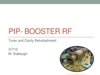
Phase Measurements For Booster RF. Victor Grzelak. Phase Measurements For Booster RF. Alignment measurements. Phase Measurements For Booster RF. Changes. Phase Measurements For Booster RF. Measurements Equipment. Synth Setup:

E N D
Phase Measurements For Booster RF Victor Grzelak Accelerator Division RF
Phase Measurements For Booster RF Alignment measurements Fermi AD/RF
Phase Measurements For Booster RF Changes Fermi AD/RF
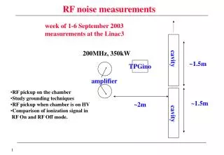
Phase Measurements For Booster RF Measurements Equipment • Synth Setup: • HP8657B Synthesizer>HP11549A R Splitter>(2)8nS Phase matched cables>A and B inputs of ENI • VVM Setup: • HPH508A VVM>(2)8nS cables • Directional couplers • At least 4 (Anode and cathode on 2 cavities) • Arbitrary waveform generator • APG,SSD,Trig1, Trig2 • DC Voltage supply 0 to +10 Fermi AD/RF
Phase Measurements For Booster RF Measurements setup • Turn all RF off (Victor) • Replace APG,SSD, Trig1 and Trig2 with ARB (Victor & John) • Replace FBS curve with DC voltage supply • Replace A/B input to ENI with fixed frequency synthesizer • 37.8, 45 and 52.808MHz • Verify with Bill location of directional couplers going to B:FOPAB • Create 5 second pulse on Arb • Measure output of the brass box, and input to the SSD with VVM Fermi AD/RF
Phase Measurements For Booster RF Tunnel Measurements • Add Directional Coupler to Cathode monitor and Anode monitor on both PAs. Terminate Anode to 50 Ohms and connect cathode to VVM of adjacent stations (Group 1) • Turn on RF • Tune up for minimized PD error • Measure cathode to cathode phase • Measure DS gap to DS gap phase • (Upstairs) Measure RCC rack at input to FB Chassis Fermi AD/RF
Phase Measurements For Booster RF Logistics • 2 VVM carts one upstairs one downstairs • Group 1 measure Brassbox and SSD input for everything upstairs • Group 2 connects directional couplers to downstairs • Group 3 is Victor and John. Who will setup all of the waveforms and the frequency synthesizer • Communication will be done with tunnel phones downstairs and walkie talkies upstairs • Each measurement should be done at all 5 locations at 3 frequencies. • This would likely take a day long shutdown Fermi AD/RF
Phase Measurements For Booster RF Measurements Fermi AD/RF
Phase Measurements For Booster RF Additional Measurements Powered Measurement • Period to Period with 32nS cables • Must phase match cables and verify this would be the proper length Unpowered measurement • Synthesizer in tunnel and measure gap and cathode cabling to upstairs • Gap phasing should be calibrated with magnitude included in measurements • Cathode phasing with VVM and NA S11 Fermi AD/RF
Phase Measurements For Booster RF Other thoughts 1.312 (Zero) 1.965 (Current) Fermi AD/RF