Systems Engineering Research Taking Systems Engineering to the Next Level
630 likes | 645 Vues
Explores evolving operating environments, networked society paradigms, decision analysis strategies, and advanced supportability methods in systems engineering. Features collaborative research insights and innovative approaches in the field.

Systems Engineering Research Taking Systems Engineering to the Next Level
E N D
Presentation Transcript
Systems Engineering Research Taking Systems Engineering to the Next Level Cihan H Dagli, PhD Professor of Engineering Management and Systems Engineering Professor of Electrical and Computer Engineering Founder and Boeing Coordinator of Systems Engineering Graduate Program INCOSE and IIE Fellow dagli@mst..edu MISSOURI UNIVERSITY OF SCIENCE AND TECHNOLOGY Rolla, Missouri, U.S.A.
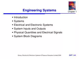
Outline • Introduction – Need for Systems Architecting and Engineering – DoD Systems Engineering Vision 2020 • Academia Needs • Missouri S&T’s Approach – Smart Systems Architecting – Courses – Industry Cooperation • Future Of Systems Architecting
Research Collaborators • Renzhong Wang (Current SysEng PhD Student, INCOSE Doctoral Award Recipient) • Dr. Atmika Singh (Former SysEng PhD Student, Researcher at Clearway Holding) • Dr. Jason Dauby (Former SysEng PhD Student, INCOSE Doctoral Award Recipient, Researcher at Naval Surface Warfare Center) • Dr. Nil Kilicay Ergin (Former SysEng PhD Student, Faculty at Pen State University)
Introduction The Dynamically Changing Operating Environment – We are increasingly a networked society: • Trans-national mega military systems • Asymmetrical threats vs. rapid reaction forces • Trans-national enterprises • Trans-national manufacturing • Globally distributed services and production – We are increasingly dependent on these networks.
Effectiveness Introduction Decision Analysis Advanced Supportability • Proactive manufacture • Proactive supply • Autonomic distribution • Spares usage & trends • Projected spares needs Competing Competing Alternatives Alternatives Alternatives Alternatives Competing Competing • Prognostics & Health Management • Opportunistic maintenance • Prognostics & Health Management • Opportunistic maintenance • Interactive Tech Manuals • Interactive Tech Manuals Multiple Multiple Participants Participants Participants Participants Multiple Multiple Multiple Multiple Objectives Objectives Objectives Objectives Multiple Multiple Decision Analysis techniques are tools used to solve complex problems through a structured process through a structured process through a structured process Decision Analysis techniques are tools Decision Analysis techniques are tools used to solve complex problems used to solve complex problems Communication Communication Repair & Overhaul Defensible Defensible Decision Analysis Decision Analysis Must Haves Must Haves POL Wishes Wishes Wants Wants Pipelines Needs Needs Desires Multiple Multiple Disciplines Disciplines Disciplines Disciplines Desires Multiple Multiple Aircraft Vehicle Equipment Generation & Maintenance Documented Documented Disciplined Disciplined Focus Focus • Flexible support • Flexible support Conflicting Conflicting Conflicting Conflicting Interests Interests Interests Interests • Consensus • Common Terminology • List of Potential Trades • Ranked Priorities • Documentation • Documentation • Consensus • Common Terminology • List of Potential Trades • Ranked Priorities COD Intermediate Repair OEM Resupply Ground Deliveries Decision Analysis Provides More Customer Decision Analysis Provides More Customer Decision Analysis Provides More Customer Decision Analysis Provides More Customer Interaction and a Better Product Interaction and a Better Product Interaction and a Better Product Interaction and a Better Product • Voice of Customer • Customer Requirements • Expert Judgment • 24/7 Response centers • 24/7 Response centers • Digital Engineering Links • Digital Engineering Links • Survivability • Vulnerability • Mission Success • Supply Chain Mgt. • Maintenance Mgt. Analysis • Supply Mgt. Analysis Unmanned Combat Air Vehicle Unmanned Combat Air Vehicle Advanced Technology Demonstration Advanced Technology Demonstration $ $ Point Point Estimates Estimates Network Network- -Centric Future Centric Future $ $ UCAV - ATD UCAV - ATD $ $ Phase II - Affordability / LCC Plan Phase II - Affordability / LCC Plan Prepared by: Prepared by: C oncurred by: C oncurred by: Approved by: Approved by: Historical Regression Regression Historical Supplier Options Options Supplier David Mc Caughey (Boeing) Affordability Plan Plan David Mc Caughey (Boeing) Affordability Kurt Bausch (Boe ing) Kurt Bausch (Boe ing) Phil Pa nagos (Boeing) Phil Pa nagos (Boeing) Time Time Steve Rast (S A IC) Steve Rast (S A IC) L t Col Mic h ae l Leahy (USAF) L t Col Mic h ae l Leahy (USAF) Cost Uncertainty Cost Uncertainty Simulation Simulation LCC Probability LCC Probability 100% 100% 80% 80% $ $ 60% 60% Focus: • System Cost Drivers • Figures of Merit • Effectiveness & Affordability Focus: • System Cost Drivers • Figures of Merit • Effectiveness & Affordability Balance Balance EMD Prod O&S O&S EMD Prod 40% 40% 20% 20% Time Time $ $ $ $ 0% 0% JSF JSF F-16 F-16 Cost Cost Targets Targets O&S Cost O&S Cost Unit Cost Unit Cost $ $ UCAV UCAV UCAV UCAV Time Time 75% Reduction from F-16 75% Reduction from F-16 1/3 the cost of JSF 1/3 the cost of JSF 1998 1998 1999 1999 2000 2000 2001 2001 2002 2002 2003 2003 2004 2004 2005 2005 1Q 2Q 3Q 1Q 2Q 3Q 4Q 4Q 1Q 2Q 3Q 1Q 2Q 3Q 4Q 4Q 1Q 2Q 1Q 2Q 3Q 4Q 3Q 4Q 1Q 2Q 3Q 1Q 2Q 3Q 4Q 4Q 1Q 2Q 3Q 1Q 2Q 3Q 4Q 4Q 1Q 2Q 3Q 4Q 1Q 2Q 3Q 4Q 1Q 2Q 1Q 2Q 3Q 4Q 3Q 4Q 1Q 2Q 1Q 2Q 3Q 4Q 3Q 4Q Development / Development / Investment Plans Investment Plans UCA V ATD Phase I Phase I UCA V ATD UCAV ATD Phase II Phase II UCAV ATD RR &OE RR &OE EMD EMD • Investment Planning Planning • Investment Establish Common Avionics D evelopment Group Single simulated vehicle distributed control lab demo control lab demo Establish Common Avionics D evelopment Group Single simulated vehicle distributed Real-time software architecture & design demo & design demo Real-time software architecture R eal-time distributed processing R eal-time distributed processing High High AJ/LPI LOS C2 Demo AJ/LPI LOS C2 Demo D eliver B-2 w eapon D eliver B-2 w eapon delivery GWIS delivery GWIS D EMPC D EMPC UD S Formation Taxi/Flight (fixed geom, pos sep algorithms) Software reuse metrics tracking Lab & flight demo - OMP/mission/vehicle systems integration AT3 or PLAID test on U CAV UD S Formation Taxi/Flight (fixed geom, pos sep algorithms) Software reuse metrics tracking Lab & flight demo - OMP/mission/vehicle systems integration AT3 or PLAID test on U CAV JSF/UCAV Commonality Study Supplier software productivity demo $ $ Decision aids for operator handoff lab demo lab demo Decision aids for operator handoff Global theater multi-level netw orking demo UCAV decision aids lab demo (contingency management) (contingency management) Global theater multi-level netw orking demo UCAV decision aids lab demo Risk Factor Risk Factor BOLDSTR OKE demos UCAV decision aids flight demo Loss of comm contingency flight demo Primary: Fully integrated softw are functionality. Decreased software BOLDSTR OKE demos JSF/UCAV Commonality Study Supplier software productivity demo Software reuse metrics tracking UCAV decision aids flight demo Loss of comm contingency flight demo Primary: Fully integrated softw are functionality. Decreased software functionality. functionality. Med Med Software reuse metrics tracking AJ/LPI BLOS C2 - AJ GPS Demo AJ GPS Demo AJ/LPI BLOS C2 - Demo of OMP & Intelligent Maintenance Aids / PMT & IMSS PMT & IMSS Demo of OMP & Intelligent Maintenance Aids / Fallback: Fallback: Drop multiple pre-planned small Drop multiple pre-planned small bombs from MBR with full SMS bombs from MBR with full SMS SAR flight test on UC AV on UC AV SAR flight test Automated dynamic mission replanning flight test demo replanning flight test demo Automated dynamic mission U CAV ATD Phase I U CAV ATD Phase I U CAV ATD Phase II Multi-sensor multi- source data fusion PH M/OMP PH M/OMP Multi-sensor multi- source data fusion U CAV ATD Phase II U CAV ATD RR &OE UDS Coordinated motion, variable geometries / deconfliction algorithms geometries / deconfliction algorithms UDS Coordinated motion, variable Low Low Time Time U CAV ATD RR &OE Gov’t S&T Gov’t S&T }UTP }UTP U DAS Algorithmic Control Flight Test Demo (Multi-Vehicle Coordinated Flight, C ollision U DAS Algorithmic Control Flight Test Demo (Multi-Vehicle Coordinated Flight, C ollision Avoidance, Sensor Planner, Autorouter) Avoidance, Sensor Planner, Autorouter) Air traffic mgt demo Air traffic mgt demo B oeing B oeing Suppliers Suppliers Flt Demo 1 Flt Demo 1 Flt Demo 2 Flt Demo 2 Flt D emo 3 Flt D emo 3 Flt D emo 4 Flt D emo 4 Flt Demo 5 Flt Demo 5 Phase II Start Last revision: Last revision: Phase II Start R R&OE Start R R&OE Start Phase II End Phase II End EMD Start EMD Start Kurt Bausch 314-232-6917 314-232-6917 Kurt Bausch • Operational C4ISR • Communications • Dynamic Systems • System of Systems • LCC/TOC • Design to Cost • Best Value • Visualize Scenarios • Immerse Man in Loop Courtesy of Dr. Mike McCoy
Introduction (Adopted from An Overview of Global Earth Observation System of Systems (GEOSS), Stefan Falke, Geospatial Intelligence Operating Unit, Northrop Grumman Corporation)
Introduction Super-Efficient , Eco-Friendly, and People Friendly Trans-national Manufacturing
Need for Systems Architecting and Engineering Systems Engineering: An interdisciplinary approach and means to enable the realization of successful systems. Systems Engineering considers both the business and the technical needs of all stakeholders with the goal of providing a quality product that meets the user needs. System Architecture: The aggregation of decomposed system functions into interacting system elements whose requirements include those associated with the aggregated system functions and their interfaces requirements/definition • • INCOSE (International Council of Systems Engineers)
Need for Systems Architecting and Engineering Cost and Schedule Performance as a Function of Systems Engineering Effort *Source: INCOSE Systems Engineering Center of Excellence SECOE 01-03 INCOSE 2003; & Honour, E. “Understanding Value of Systems Engineering”, INCOSE Conference, June 20-24, 2004
Need for Systems Architecting and Engineering • Performed by NDIA in conjunction with the SEI in 2006-2008 • Surveyed 64 projects at defense contractors to assess: • Data was collected anonymously to encourage honest and accurate reporting. • • Results published at: http://www.sei.cmu.edu/publications/d ocuments/08.reports/08sr034.html *Source: Presentation of Joe Elm from Software Engineering Institute Carnegie Mellon University
Need for Systems Architecting and Engineering PROJECT PERFORMANCE vs. TOTAL SE CAPABILITY 1.00 12% Best Performance ( x > 3.0 ) 15% 0.75 56% 46% 59% Moderate Performance ( 2.5 x 3.0 ) 0.50 13% 0.25 Lower Performance ( x < 2.5 ) 39% 31% 29% 0.00 Lower Capability Moderate Capability Higher Capability Gamma = 0.32 p = 0.04 ( x 2.5 ) N = 13 (x 3.0 ) N = 16 ( 2.5 < x < 3.0 ) N = 17 *Source: Presentation of Joe Elm from Software Engineering Institute Carnegie Mellon University
Need for Systems Architecting and Engineering *Source: Presentation of Joe Elm from Software Engineering Institute Carnegie Mellon University
Need for Systems Architecting and Engineering *Source: Presentation of Joe Elm from Software Engineering Institute Carnegie Mellon University
Need for Systems Architecting and Engineering • Architectures are fundamental to the success of the program • Architecture selection is a search process based on ambiguous information and data • Architecture selection requires assessment methods based on ambiguous key performance parameters to identify compromise architecture • Architecting process is reduction of ambiguity hierarchically
DoD Systems Engineering Vision 2020 • Design Principles – Platform Based Engineering Using a common core platform to develop many related systems/capabilities – Trusted System Design Developing trusted systems from untrusted components
DoD Systems Engineering Vision 2020 • Design Framework – Model Based Engineering Using modeling and simulation for rapid, concurrent, integrated system development and manufacturing
DoD Systems Engineering Vision 2020 • Adaptable DoD Systems – Capability on Demand Real-time Adaptive Systems Rapidly Reconfigurable Systems Pre-planned Disposable Systems
Academia Needs • Systems Architecting Laboratory: Real Engineering Problems and Customer • Environment to demonstrate, value of systems engineering and new systems architecting approaches on real systems of various size • Close cooperation with industry honoring propriety nature of information and data • Dissemination channels for new research
Missouri S&T’s Approach Systems Architecting Research
Smart System Architecting • How can we assess architectures? • How can we represent architectures? • How can we generate architectures? • How can we reduce ambiguity hierarchically? • How can we test architectures for correctness? • What are the tools of architect?
Smart Systems Architecting C. H. Dagli, A. Singh, J. P. Dauby, R. Wang, “Smart systems architecting: computational intelligence applied to trade space exploration and system design,” Systems Research Forum ,Vol. 3, No. 2 (2009) 101–119
DoD Systems Engineering Vision 2020 • Design Framework – Model Based Engineering Using modeling and simulation for rapid, concurrent, integrated system development and manufacturing
Smart Systems Architecting 1. What constitutes the “best” in architecture? 2. What is the measure for comparing architectures? 3. We can search for the “best” architecture, as long as we can define “best” 4. Can we associate an aggregate value in evaluating functional architectures? 5. How can we deal with the ambiguity of need requirements and performance measures in the search process? 6. Is there a way to mathematically represent functional architectures? 7. Can we generate architectures through a evolutionary process? 8. Can we integrate the architect in evolutionary architecting process? C. H. Dagli, A. Singh, J. P. Dauby, R. Wang, “Smart systems architecting: computational intelligence applied to trade space exploration and system design,” Systems Research Forum ,Vol. 3, No. 2 (2009) 101–119
Smart Systems Architecting PERFORMANCE PERCEPTIONS SCHEDULE COST RISK FACTS What is the measure for comparing architectures?
Smart Systems Architecting Adaptability Robustness Affordability Flexibility Survivability Reliability What is a reasonable approach to find and aggregate measure for comparing architectures?
Smart Systems Architecting Super-Efficient , Eco-Friendly, and People Friendly Top level system attributes
Smart Systems Architecting (SSA) SSA Approach Fuzzy Assessment and Computing with words Evolutionary Algorithms for Architecture Canonical Decomposition Fuzzy Comparison (CDFC) Self Organizing Maps for Clustering Architecture Families Models for Behavior Modeling C. H. Dagli, A. Singh, J. P. Dauby, R. Wang, “Smart systems architecting: computational intelligence applied to trade space exploration and system design,” Systems Research Forum ,Vol. 3, No. 2 (2009) 101–119
Fuzzy Assessment and Computing with Words Modern large-scale systems are comprised of many interacting subsystems and components and exhibit complex behavior. This nonlinear behavior cannot be analyzed using traditional modeling approaches. Fuzzy Cognitive Maps based methodology can be for assessing the inherent value of candidate architectures early in the design lifecycle. A. Singh and C. H. Dagli, “"Computing with words" to support multi-criteria decision making during conceptual design,” Systems Research Forum, vol. 04, no. 01, p. 85, 2010.
Fuzzy Assessment and Computing with Words The system and its components are represented in the form of a directional graph where the nodes represent system components and the arcs represent their interactions. This modeling approach makes use of the “computing with words” (CW) paradigm to use human experience to assign linguistic weights to the arcs based on the strength of influence between connected nodes. An overall value measure for a system can be derived by simulating the resulting graph. Such an approach will facilitate the selection of the best set of architectures or component technologies during the nascent design stages based on the value delivered to the stakeholder. A. Singh and C. H. Dagli, “"Computing with words" to support multi-criteria decision making during conceptual design,” Systems Research Forum, vol. 04, no. 01, p. 85, 2010.
Evolutionary Algorithms for Architecture Once architecture options have been identified using FCM and CW, evolutionary algorithms can be employed to find the right combination of technologies to utilize in a system design. Functional architecture chromosome
Canonical Decomposition Fuzzy Comparison (CDFC) The CDFC methodology is a new architecture assessment approach offering increased objectivity, fidelity, and defensibility in comparison to traditional approaches. The methodologyconsists of four elements: •Extensible modeling – facilitates the exchange of data between model resolution levels. •Canonical design primitives – basic representations of system-component technologies. •Comparative analysis – comparison between heuristic and canonical embodiments. •Fuzzy inference – a mapping from system response features to fuzzy sets describing the architecture assessment. J. P. Dauby, “Assessing system architectures: the canonical decomposition fuzzy comparative methodology,” Ph.D. dissertation, Dept. Eng. Management and Sys. Eng., Missouri University of Science and Technology, Rolla, MO, 2011.
Canonical Decomposition Fuzzy Comparison (CDFC) Architecture Assessment Physical Architecture 4 1 2 4 3 Decomposition Using Canonical Primitives Fuzzy Feature Interpretation 1 3 2 Comparative Analysis: Isolated vs. Integrated Performance Architecture assessment for airborne wireless systems in conjunction with a potential Acquisition Category (ACAT) ID program for the Department of the Navy J. P. Dauby, “The canonical decomposition fuzzy comparative approach to assessing physical architectures,” INSIGHT, vol. 13, no. 3, pp. 60-62, Oct. 2010.
Self Organizing Maps for Clustering Architecture Families Architecture solution candidates are described by functional, logical, or physical properties including integration sensitivity. The set of properties for each candidate are used as the input vector to a variety of SOM algorithms. The SOM output can identify design features and group potential architectural concepts into families based on common features, sensitivities, or tendencies. This approach facilitates the development of architecture families that exhibit similar behavior as well as identify combinations of technologies that work well together.
Models for Behavior Modeling Motivation Introduce dynamic model analysis into architecture modeling. Facilitate system behavior, performance, and effectiveness analysis, architecture evaluation, and functionality verification and validation. Renzhong Wang and Cihan H. Dagli, “Executable System Architecting Using Systems Modeling Language in Conjunction with Colored Petri Nets in a Model Driven Systems Development Process.” Journal of Systems Engineering, Vol. 14(3), 2011
Models for Behavior Modeling Requirement Analysis and Specification Formal Model Modeling SysML Diagrams Start Requirements Analysis Model Transformation Desired Behavior Executable model CPN Refinement Architecture Analysis and Evaluation Behavior analysis Simulation Interactive GUI End Functionality verification External Application Architecture refinement & reconfiguration Behavior as modeled Renzhong Wang and Cihan H. Dagli, “Executable System Architecting Using Systems Modeling Language in Conjunction with Colored Petri Nets in a Model Driven Systems Development Process.” Journal of Systems Engineering, Vol. 14(3), 2011
Models for Behavior Modeling • OMG (Object Management Group), Semantics of a Foundational Subset for Executable UML Models, Version 1.0 Beta 3, ptc/2010-03-14, http://www.omg.org/spec/FUML/1.0/Beta3/, 2010a • Foundational UML Reference Implementation, http://portal.modeldriven.org/project/foundationalUML – Specify and demonstrate the semantics required to execute activity diagrams and associated timelines per the SysML v1.0 specification – Specify the supporting semantics needed to integrate behavior with structure and realize these activities in blocks and parts represented by activity partitions Renzhong Wang and Cihan H. Dagli, “Executable System Architecting Using Systems Modeling Language in Conjunction with Colored Petri Nets in a Model Driven Systems Development Process.” Journal of Systems Engineering, Vol. 14(3), 2011
Models for Behavior Modeling • “Behavioral Formalism” refers to a formalized framework for describing behavior, such as state machines, Petri nets, data flow graphs, etc. – UML/SysML, modeling language weak in executable semantics – Supplemented by Semantics of a Foundational Subset for Executable UML Models • Software that implemented behavioral formalism – CORE, IBM Rational Rhapsody, CPN Tools, etc. Renzhong Wang and Cihan H. Dagli, “Executable System Architecting Using Systems Modeling Language in Conjunction with Colored Petri Nets in a Model Driven Systems Development Process.” Journal of Systems Engineering, Vol. 14(3), 2011
Models for Behavior Modeling • Combined usage of related tools. – Three basic functions of a model: • Specification (of a system to be built), – UML and SysML • Presentation (of a system to be explained to other people, or ourselves), – DoDAF products • Simulation. – Petri nets, DEVS (Discrete Event Specification System – xUML, XTUML, VM, Business Process Modeling Notation/Business Process Execution Language BPMN /BPEL • Extract key information from simulation to support architecture evaluation and analysis. • Refine the architecture design based on analysis results. Renzhong Wang and Cihan H. Dagli, “Executable System Architecting Using Systems Modeling Language in Conjunction with Colored Petri Nets in a Model Driven Systems Development Process.” Journal of Systems Engineering, Vol. 14(3), 2011
DoDAF 2.0 Architecture Viewpoints and DoDAF-described Models DoD Architecture Framework Version 2.0 Volume I
Architecture Presentation Techniques DoD Architecture Framework Version 2.0 Volume I
Architecture Analytics DoD Architecture Framework Version 2.0 Volume I
Executable Modeling Formalisms • The chosen of executable modeling language depends on the system to be modeled, the abstraction level to work on, and the system behavior of interest. Many modern distributed systems can be best specified by discrete event models because – The behavior of these systems is driven only by events that occur at discrete time points. Discrete-event models* represent the operation of a system as a chronological discrete sequence of events. Each event occurs at an instant in time and marks a change of state in the system. An executable architecture is a dynamic model that defines the precise event sequences, the conditions under which event is triggered and information is produced or consumed, and the proprieties of producers, consumers and other resources associated with the operation of the system. • • • * Banks, J. Discrete-event System Simulation. Pearson Prentice Hall, Upper Saddle River, NJ. 2005.
Colored Petri Nets (CPNs) Places carry makers, called tokens, which mark the state of a system. Transitions describe the actions of the system When certain conditions hold, transitions will be fired, causing a change in the placement of tokens and thus the change of system states. Arcs tell how actions modify the state and when they occur 1 1`”data” 1. Combining a well-defined mathematical foundation, an interactive graphical representation, and the capabilities to carry out simulations and formal verifications. The same models can be used to check both the logical or functional correctness of a system and for performance analysis. CPNs are very flexible in token definition and manipulation. 2. 3.
Executable Semantics Place (w tokens) Place (w tokens) CPN Transition System Conditions Event Effects Action / Activity (a set of actions) Input Data/Information Control signals Resources Other Output Data/Information Control signals Resources Other •Time Delay •Post conditions Discrete Event System Specification Transition State State Relationships between CPN Artifacts, System Entities and Discrete Event System Specifications
Models for Behavior Modeling Meta-Architecture System 1 System 4 Net-Centric Architecture G I G Robust Adaptable System 2 System n-1 Modular Flexible System 3 System n Interoperable Dynamically Changing Meta-Architecture for Complex Systems
Models for Behavior Modeling • For modeling the meta-architecture – Multi-agent based modeling • Agents • Environment • Interactions • For modeling sub-system architectures – Cognitive architectures N. Kilicay-Ergin “Architecting System of Systems: Artificial Life Analysis of Financial Market Behavior”, PhD Dissertation Dept. Eng. Management and Sys. Eng., Missouri University of Science and Technology, Rolla, MO, 2007
System-of-Systems System Level Behavior Environment Level Dynami cs Semantics Selection Criteria Meta-architecture Agent Level Agent 1= System 1 Agent 2= System 2 Agent 3= System 3 Agent n= System n Cognitive Level* Meta-management Perception Action Deliberative Reasoning Sub-system architectures Reactive Mechanism *Sloman’s H-Cogaff architecture, 2000 Mechanism Modules Long-term Associative memory Imitation Short-term memory Bias Attention filter Computational Intelligence Toolbox Neural Networks Genetic Algorithm Learning Classifiers Reinforcement Learning Swarm Intelligence
Missouri S&T’s Approach Degrees and Graduate Certificates
Systems Engineering Degrees • MS in Systems Engineering – Architected based on a need statement of invited Boeing RFP in 1998. – Since the inception of the program on Spring 2000 semester 410 engineers have received their M.S. degrees. – Ten courses – six core and four engineering specialization- are required for the degree. • PhD in Systems Engineering – One graduate from Boeing Seattle out of four graduates since 2006 – Fifteen students currently in the program
Systems Engineering MS Degree Curriculum Core Courses Systems SysEng 469 – Systems Architecting Systems Architecture SysEng 368 – Systems Engr. and Analysis I Systems Engineering and Analysis Systems Engineering – Information Based Design SysEng 468 – Systems Engr. and Analysis II Complex Systems Management SysEng 413 Economic Analysis for Systems Engineering Economic Decision Analysis SysEng 412 Complex Engineering Systems Program Mgt. Systems Engineering Mgt. Organizational Behavior and Management SysEng 411 Systems Engineering Capstone