Download
1 / 81
2.76k likes | 6.06k Vues
Basic Concepts of Design & Construction of Gas Distribution Network. GSPC Gas Company Limited December, 2009 Gandhinagar. City Gas Distribution – An Overview. WHAT IS CITY GAS DISTRIBUTION?.

E N D
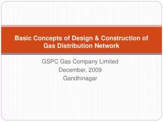
Basic Concepts of Design & Construction of Gas Distribution Network GSPC Gas Company Limited December, 2009 Gandhinagar
WHAT IS CITY GAS DISTRIBUTION? CGD is the last component of the Natural Gas value chain delivering Natural Gas to end users in town and cities to meet the demand for a cleaner, more efficient, economical and environmentally-friendly energy source.
CITY GAS DISTRIBUTION CONCEPT • Development of Pipeline Network in a pre-defined geographical spread • Maintaining Different Levels of Gas Pressure to meet the Demand of various segments of gas users - Domestic, Commercial, Industrial and Automobiles. • Designing high pressure and medium pressure network such that supply to any consumer is possible from either side. • Design gas storage / Gas sourcing for maximum survival period • Consider Health, Safety & Environment at all stages
Steps in the design of Gas Distribution System Market demand estimated based on comprehensive field survey of units covering domestic, commercial, industrial and transport sectors. Demand forecast projection is carried out for 20-25 years. Peak hour consumption estimated for network design. The system is to be designed based on 20-25th year projected demand at peak load in a phased manner. Reconnaissance Route Survey within the town to identify suitable routes for laying pipelines, locations for City Gate Station, District Regulating Station & CNG Station
Network design and optimization with available software Design of Mother Station and Daughter / Daughter booster station for CNG supply to automobiles National / International standards adopted for design. Project implementation done subsequently. Steps in the design of Gas Distribution System
Transmission Line Distribution Zone City Gate Station Battery Limits Transmission Distribution
HP Network CITY GATE MPB Network CNG Mother Stations DRS DRS DRS MPA Network Domestic and Commercial Users LP Network CGD SYSTEM BASIC CONCEPT
CGD - Infrastructure Major Constituents of CGD are; • City Gate station • Pipeline Network • Steel Pipelines • Poly Ethylene Pipelines • GI / Cu Pipes • Regulating Stations • District Regulating Stations • Service Regulators • Domestic / Commercial / Industrial Regulators • Metering Stations / Metering & Regulating Stations • CNG Stations
CITY GATE STATION (CGS) • CGS is the location of Custody Transfer from Transmission Company to Distribution Company.
CITY GATE STATION (CGS) • Inlet & Outlet isolation valves • Knock Out Drum (KOD), If required • Filter • Metering Unit (Turbine / Orifice / Ultrasonic) • Gas Chromatograph (GC), If required • Pre-heater (if required) • Pressure reduction skid comprising • Active & monitor Regulators • Stream discrimination arrangement • Slam shut valve for over & under pressure protection • Creep relief valves. • Odorising Unit
STEEL PIPELINE • The Steel Grid pipeline sizes is 12”NB & 8”NB whereas, spur lines shall be of 6”NB & 4”NB. • Steel pipelines used in the distribution system is fully coated. The coating is extruded polyethylene, with each weld joint coated with either heat shrink sleeves or field applied tape. • Prior to the pipeline being put into service, the distribution pipeline to be non-destructively tested by two methods. Firstly, welds would be radio graphed and, secondly, the completed pipeline extension would be hydro-statically tested at a higher pressure than its operating pressure. • After hydrostatic testing, the pipeline to be dried, purged and filled with natural gas. The testing and commissioning procedures will be detailed during the detailed design phase of the project.
STEEL PIPELINE • To protect the pipeline from corrosion, a cathodic protection (CP) system of impressed current is proposed. During the detailed design phase, the CP capability of the existing transmission system will be investigated to establish if it has the capacity to provide CP to the extension. If it is found that the existing system does not have the capacity, additional CP facilities will be designed. • The steel grid is installed at a minimum depth of 1.0 meter cover, and in accordance with Indian requirements.
MDPE PIPELINE • The distribution pipe is with Standard Dimension Ratio (SDR 9) for 20 mm, (SDR) 11 from 32 mm up to 63 mm & (SDR) 17.6 for above 63 mm. The term SDR is defined as the normal outside diameter (DN) divided by the minimum wall thickness. • It is standard practice in India to have a minimum 1.0 meter cover. This additional depth in a densely populated area would be recommended. • All MDPE pipe back filled with sand around it to protect the plastic material.
Medium Density PolyEthylene (MDPE) Pipes • Tech Spec: IS 14885:2001 & ISO 4437 • Material Grade & Color: Internationally approved resins of PE 100 grade of Orange color • Minimum Required Strength (MRS) of PE 100 grade pipe: 10 MPa • Pressure Class: SDR 9 (dia 20 mm), SDR 11 (dia 32 & 63 mm) and SDR 17.6 (dia 90, 110, 125 and 160 mm). • Operating pressure: 4 bar (g). • Operating temperature range: - 10 0 C to + 40 0 C.
Advantages of PE pipes • High performance (Globally proven leak free system) • More Flexibility, coil ability, ductility, High elasticity • Low density (low weight, high strength to weight ratio) • High resistance to corrosion • Low heat conductivity (small thermal loss) • Smooth surfaces (low pressure losses due to low pipe friction) • Easy to transport, handle and lay • Longer life
Advantages of PE pipes • Easier and speedier joining techniques to ensure leak tight joints by employing electro fusion techniques • Higher productivity, i.e., reduction in installation time (15 minutes in case of PE against 4 hours in case of steel), thereby lesser inconvenience to public • Reduced number of joints, hence safer and leak free system • Less time is consumed to repair PE damages as compared to steel damages • Good squeeze off properties
Advantages of PE pipes • Longer design life of PE pipes (50 years) as compared to steel pipeline (30 years) • Avoidance of NDT techniques in building premises, which is very critical • Size of trench is less in case of laying of PE pipe as compared to steel
MDPE Fittings • Tech Spec: ISO 8085-3 or EN 1555-3 • Material Grade: PE 100 • Terminal pin size: 4 or 4.7 mm • Voltage: 39 – 40 Volts. • Color: Black.
PE Stop Off Valves (Typical) • Standard: ASME B 16.40, EN 1555-4 • Pressure Class: SDR 11. • Design Pressure: 5.5 bar (g). • Design Temperature: 45 0 C. • Operating Temperature: 10 0 C to 45 0 C • End Connections: PE Material (Spigot Type) • Stem Extension: Integral stem extension required (Minimum 690 mm from the Top of Pipe) • Valve Design: One piece construction. • Ball position Indicator: Open / Close limits required.
Crimping Fitting (Typical specification) • Used to connect u/g PE pipes with a/g GI pipes • Operating Pressure: up to 4 bar (g) • Operating Temperature: 40 0 C • Hydrostatic Test Pressure: Minimum hold Pressure of 10 bar (g), for 1 hour duration • Pneumatic Test Pressure: Minimum pressure of 6 bar (g), for 1 hour duration • Pull out Test: • Shall not fracture within the jointed assembly • Shall withstand the Pneumatic pressure leak test • Shall not leak
Typical requirements of Pressure Regulators used for domestic and small I&C customers • Maximum Inlet Pressure: Maximum 4 bar (g) • Nominal Outlet Pressure: 100 mbar (g) • Flow capacities: 50, 150, 200, 250 scmh • End connections: Threaded (& Tapered) as per BS 21 • Operating ambient temperature: up to 45 0C • Lockup: Maximum pressure, under no-flow condition, up to 125 mbar (g) • Creep relief valve: To protect against downstream over pressure at low flows or in the event of valve seat malfunction, preset to 140 mbar (g) • Over Pressure Shut Off (OPSO): Device to protect against downstream over pressure, preset to 160 mbar (g) • Under Pressure Shut Off (UPSO): Device to protect against downstream under pressure with a pressure setting range 40 mbar (g) to 65 mbar (g)
Regulator Selection • Information required to select a regulator: • Maximum and Minimum inlet pressure • Required outlet pressure • Maximum flow rate • Tolerance on outlet pressure • Size of pipework • Type of gas • Safety features required • Size of orifice • OPSS, UPSS & Relief settings • Installation indoors of outdoors • Orientation of regulator
Gas Meters The most common types of meters used are: • Diaphragm • Rotary Positive Displacement (RPD) • Turbine
Diaphragm Gas Meters (Domestic) • Tech Spec: EN 1359 • Capacity: 2.5 m3/hr • Rangeability or TD ratio: 1:150 or better • Nominal Working Pressure: 21 mbar (g) • End Connections: ¾”, as per BS 746 (Male) • Center to Center distance: 110 mm between inlet and outlet connections
Diaphragm Gas Meters (Commercial) • Tech Spec: EN 1359 • Capacity: 10, 25, 40, 65 scmh • Rangeability or Turn Down ratio (ratio of Qmax and Qmin): 1:150 or better • Nominal working Pressure: 100 mbar (g) • Pressure rating : Suitable to withstand maximum working pressure of 200 mbar (g)
Rotary Positive Displacement (RPD) meters • Tech Spec: EN 12480 • Volumetric meter • Appropriate for medium size load • Typical Turndown 35:1 to 50:1 • Accuracy ±1% • Large measuring range • Not sensitive against disturbances • Not sensitive against fast changes in flow rate • Needs lubrication
Advantages Disadvantages Good flow turndown Filtration essential (50 microns or finer) Tolerance to installation effects and load behaviour Requires lubrication Accuracy ±1% Physical size at large capacities Much smaller than a diaphragm meter Can create pressure fluctuations on on/off loads Very long life Can cut off gas supply when it fails Expensive Rotary Positive Displacement (RPD) meters
Industrial Metering Station (IMS) • IMS are used to measure gas supplied to Industrial consumers • Main component in IMS is filter, Isolation Valves, RPD Meters with EVC & Modem, Regulators (If low pressure requirement) and Non return Valve • Inlet pressure range – 1.5 Barg to 4 Barg • Outlet pressure – As required by customer
MRS components • Inlet & Outlet isolation valves • Filter • Pressure regulator with a built in slam – shut device • Relief valve • Strainer • Flow Meter (RPD, Turbine, etc.)
GI ERW Pipes • Tech Spec: IS 1239 (Part 1) • Types used: Medium Class and Heavy Class • Material: IS 1387 • Pipes shall be screwed with Taper threads • Threads: Tapered and conforming to BS 21 • Galvanizing: IS 4736 • Coating requirements: Mass of coating is 400 gms / m2 • Test Pressure: 5 MPa • Powder Coating: • Powder Material: Pure Polyester • Application: Electrostatic spraying (40 – 90 KV, Manual / Automatic)
GI Fittings (Malleable Cast Iron) • Tech Spec: IS 1879 • Material: IS 2108 Grade BM 290 • Dimensions: IS 1879 • Threads: IS 554 • All Internal & External Threads shall be tapered • Chamfer shall have included angle of 900 +/- 50 for Internal threads & 700 +/- 100 for external threads • Galvanizing: IS 4759 • Coating requirements: Mass of coating is 700 gms / m2.
Forged Fittings (Wrought Steel Iron) • Tech Spec: IS 1239 Part 2 • Material: IS 1387 • Dimensions & Tolerances: IS 1239 Part 2 • Threads: IS 554 • All Internal & External Threads shall be tapered • Chamfer shall have included angle of 900 +/- 50 for Internal threads & 700 +/- 100 for external threads • Galvanizing: IS 4759 • Coating requirements: Mass of coating is 700 gms / m2.
Brass Valves(Meter Control Valves, Riser Isolation Valves & Appliance Valves) • Tech Spec: EN 331 • Pipe Nominal Diameter :- ¼” to 2” NB. • Operating Pressure: 4 bar (g). • Operating Temperature: 10 – 60 0 C. • Material: Nickel Plated Forged Brass. • Pattern: Full Bore, Quarter Turn Ball Valve. • Handle: Suitable Metallic Handle, Lever / Knob / Cap Type with yellow coating (Powder / Plastic) on Surface marked as “GAS” • End connection: Screwed, As per BS EN 10226-1, Tapered Threaded, Female