Download
1 / 76
890 likes | 1.33k Vues
Satellite Remote Sensing 1. Types of Remote Sensing Based on Source of Energy Platform 2. Types of Satellite 3. Types of Sensors 4. Limitations of Remote Sensing 5. Basic Components of an Ideal Remote Sensing System 6. Resolution Definition and types.

E N D
Satellite Remote Sensing 1. Types of Remote Sensing Based on Source of Energy Platform 2. Types of Satellite 3. Types of Sensors4. Limitations of Remote Sensing5. Basic Components of an Ideal Remote Sensing System6. Resolution Definition and types.
Introduction to Remote sensingRS System capture radiation in different wavelength reflected/ emitted by the earth’s surface features and recorded it either directly on the film as in case of aerial photography or in digital medium letter is used for generating the images. R.S. provides valuable data over vast area in a short time about resources, meteorology and environment leading to better resource management and accelerating national development.
The four organizations are engaged in remote sensing related activities besides several other central and state gov. and educational institutes:-1.ISRO 2.SAC3.NNRMS4.NRSA
Remote Sensing - Remote sensing is defined as the science which deals with obtaining information about objects on earth surface by analysis of data, received from a remote platform. Remote sensing can be either passive or active. Active systems have their own source of energy whereas the passive systems depend upon the solar illumination or self emission for remote sensing Principles of Remote Sensing Detection and discrimination of objects or surface features means detecting and recording of radiant energy reflected or emitted by objects or surface material. Different objects return different amount and kind of energy in different bands of the electromagnetic spectrum, incident upon it. This unique property depends on the property of material
Stages in Remote Sensing1. Emission of electromagnetic radiation, or EMR (sun/self- emission)2.Transmission of energy from the source to the surface of the earth, as well as absorption and scattering3. Interaction of EMR with the earth's surface: reflection and emission4. Transmission of energy from the surface to the remote sensor5. Sensor data output6. Data transmission, processing and analysis
Aerial Remote SensingAerial photography is the most commonly used form of remote sensing and is widely used for topographic mapping, surveys for geological, soil and forestry mapping, engineering, town planning and environmental surveys on larger scale.
Remote Sensing Satellites As is known to us, many countries around the globe now have remote sensing satellite programs for land resources survey, environmental impact assessment, weather forecasting and ocean science studies. METSAT satellite programs for weather monitoring and LANDSAT satellite program for land resources surveys, both launched by the USA since 1960 and 1972.
France has also started an ambitious 'SPOT' satellite series program with the launching of SPOT-1 on 22nd February, 1986. Japan has launched Marine Observation Satellite (MOS-1) on 19th Feb. 1987. RADARSAT is Canada's first remote sensing satellite launched during 1990. European Space Agency (ESA) has launched Earth Resources Satellite (ERS-1) in 1991. India has launched a number of experimental remote sensing satellites, Bhaskara-I (June, 1979) and Bhaskara-II (Nov., 1981), Indian Experimental Satellite
INSAT series of satellite, multipurpose Geostationary satellite program, has among many sensors, (i) Very High Resolution Radiometer (VHRR) and (ii) Data Collection System
Details of IRS Series of Satellites IRS 1A 1988 1B 1991 1C 1995 1D 1997 P6 2003 cartosat1-2005 cartosat2-2007
Satellite Data Receiving StationThe Govt. of India authorized NRSA to set up a Satellite Receiving Station to receive digital data from LANDSAT series of Satellites launched by NASA/USA. This LANDSAT Receiving Station started functioning since January, 1980 situated at Shadnagar, 55 km. south of Hyderabad.
Data Acquisition Systems In Remote Sensing two types 1. Image forming ( active sensor system photography) 2. non image forming (passive sensor system satellite digital mode)
Imaging (Image forming)Image forming systems are again of two types - framing type and scanning type. In the framing type, entire frame of image is acquired instantaneously in the basic image unit e.g. in a frame camera used in photography. In scanning type, the information is acquired sequentially from the surface in bits of picture elements or pixels, point by point and line by line, which may be arranged after acquisition into a frame format
Non imaging type of sensors, are used to record a spectral quantity or a parameter as a function of time or distance ( such as Gamma radiation, magnetic field, temperature measurement etc.) They are mostly used for ground observation and in study of atmosphere and meteorology. These sensors do not form image and as such, are not used in operational remote sensing but give detailed information on spectral characteristics of the target .Such data is collected by sensor system in satellite and transmitted to earth, where it is received and recorded at Ground Station.
Characteristics of LISS-3/ LISS-4 LISS-3 Spectral Bands B2 0.52-0.59 μm B3 0.62-0.68 μm B4 0.77-0.86 μm B5 1.55-1.70 μm LIV B2 0.52-0.59 μm B3 0.62 - 0.68 B4 0.77 - 0.86spatial resolution L3 23.5 m for bands 2,3,4 70.5 m for band 5 L4 5.8 m (at nadir) Equivalent focal length (bands 2, 3, 4/ band 5) 347.5 mm/301.2 mm Swath 141 km for bands 2,3,4 148 km for band 5 23.9 km MS mode 70 km PAN mode
Satellite Data is recorded and products are available on following media Satellite data products are available in the following types of formats - High Density Digital Tape (HDDT) Quick Look Film Computer Compatible Tape(CCT), Digital Audio Tape(DAT) Compact Disc(CD-ROM) 70 mm film 240 mm Black and White film positive/negative in individual band. Black and White paper prints & enlargement in individual band 240 mm False Colour Composite (FCC) Film
TYPES OF SENSORS:-Optical Sensors used in remote sensing systems MSST MHRVLISS I.IILISS IIILISS IVPANWIFS
Remote Sensing SensorsSensor is a device that gathers energy (EMR or other), converts it into a signal and presents it in a form suitable for obtaining information about the target under investigation. These may be active or passive depending on the source of energy Sensors used for remote sensing can be broadly classified as those operating in Optical Infrared (OIR) region and those operating in the microwave region. OIR and microwave sensors can further be subdivided into passive and active
Active sensorsuse their own source of energy. Earth surface is illuminated through energy emitted by its own source, a part of its reflected by the surface in the direction of the sensor is received to gather the information. Passive sensors receive solar electromagnetic energy reflected from the surface or energy emitted by the surface itself. These sensors do not have their own source of energy and can not be used at night time, except thermal sensors. Again, sensors (active or passive) could either be imaging, like camera, or Sensor which acquire images of the area and non-imaging types like non-scanning radiometer or atmospheric sounders.
Sensors which operate in this region are :Aerial cameras : 0.38 um to 0.9 umThermal scanners : 3 um to 5 um : 8 um to 16 um Multi spectral scanner : 0.3 um to 1.1 umMicrowave wavelengths : 1mm to 1 meter (Sensors which operate in these wavelengths / frequencies are mostly active systems like RADAR)
Multispectral Scanner (MSS) used in Landsat series satellites i) Multispectral scanner (Optical MechanicalScanner)onboard Landsat series of satellites of U.S.A. (L1, L2, L3, L4 & L5) gives line scan type imagery using an oscillating mirror to continuously scan the earth surface perpendicular to the spacecraft velocity. Six lines are scanned simultaneously in each of the four spectral bands for each mirror sweep. Spacecraft motion provides the along-track progression of the scan lines. Radiation is sensed simultaneously by an array of six detectors each of four spectral bands from 0.5 to 1.1 micrometers. The detectors’ outputs are sampled, encoded and formatted into continuous digital data
(ii)Thematic Mapper (TM) usedin Landsat series satellites Landsat 4 & 5 have onboard a new payload called "Thematic Mapper" with 7 spectral bands & ground resolution of 30 meters. This is in addition to the MSS payload which is identical to those carried onboard Landsat 1 & 2 and replaces RBV payload. TM is also an Optical Mechanical Scanner, similar to MSS; however, being a 2nd generation line scanning sensor, it ensures better performance characteristics in terms of (i) improved pointing accuracy and stability, (ii) high resolution, (iii) new and more number of spectral bands, (iv) 16 days repetitive coverage (v) high scanning efficiency using bi-directional scanning and (vi) increased quantization levels. For achieving the bi-directional scanning, a scanline corrector (SLC) is introduced between the telescope and focal plane. The SLC ensures parallel lines of scanning in the forward and reverse direction.
iii)High Resolution Visible (HRV) Imager usedin SPOT Satellite The French SPOT-1 spacecraft carries two nominally identical High Resolution Visible (HRV) imagers, which can be operated independently or in various coupled modes. In contrast to the oscillating mirror design used in the Landsat imaging system, HRV cameras use Charge Coupled Devices (CCD) array as the sensing element for the first time in space environment. Each of the two cameras can be operated in either multispectral (20 m resolution) mode or panchromatic (10 m resolution) mode. The swath covered is 60 Km; and the cameras can be tilted offset upto 27° on either side of Nadir. Thus any point within a width of 950 km., centered on the satellite track can be observed by programmed camera control. SPOT-1 has stereo coverage capability in orbit with tiltable cameras, which again provides stereo image pair al most similar to metric camera air photo.
(iv)Linear Image Self Scanning (LISS) Camera used in IRS-1A ,1B Indian Remote Sensing Satellite (IRS-1A) fully designed and fabricated by the Indian Space Research Organization (ISRO) was launched on March 17th, 1988 by Russian launcher. It has four spectral bands in the range of 0.45 to 0.86 μm (0.45 to 0.53 μm to 0.59 μm, 0.62 to 0.68 μm and 0.77 to 0.86 μm) in the visible and near infrared range with two different spatial resolution of 72.5 m. and 36.25 meter from one no. of open LISS-1 and two nos. of LISS-2 cameras respectively. It provides repetitive coverage after every 22 days. Like all other LANDSAT/ SPOT missions which are designed for global coverage IRS is also in sun synchronous, polar orbit at about 900 km altitude and cover a width of 148 km. on ground. It uses linear array detectors (CCD) like SPOT.
v)Linear Imaging Self Scanning Camera-3 (LISS-3This camera is configured to provide imageries in three visible bands as well as in short-wave infrared band. The resolution and swath for visible bands are 23.5 m and 142 km, respectively. The detector is a 6000 element CCD based linear array with a pixel dimension of 10μm by 7 μm. The detector is placed at the focus of a refractive type optical system consisting of eight lens elements, which provides a focal length of 360 mm. The processing of the analogue output video signal is similar to that of PAN. For this camera, a 7-bit digitization is used which gives an intensity variation of 128 levels.
Linear Imaging Self-Scanning Camera-4 (LISS-4)LISS-4 camera serves the dual purpose of acquiring 70 km swath, mono images giving continuity to the PAN camera of 1C/ 1D. In its normal mode it acquires 23 km swath 3 band multispectral imagery, which can be positioned anywhere in the 70 km coverage of Mono mode. The enhanced dynamic range of 10 bits is intended to serve the worldwide requirement of radiometric ranges. The stereo capability of 1C/ 1D is retained to provide the across track stereo to the requirement of the users.
Panchromatic camera (PAN) The PAN camera is configured to provide the imageries of the Earth in visible spectrum, in a panchromatic band (0.5-0.75 m) with a geometric resolution of greater than 10 m and a swath of 70 km. The camera uses an off-axis reflective type optics system consisting of three mirrors for providing the required focal length. A 7μm pixel sized CCD is being used as the detector element. Using three linear array charge-coupled detectors covers the total swath of 70 km and each of these detectors covers aswath of about
The central detector is offset from the other two detectors by a distance in focal plane that corresponds to 8.6 km on the ground. The other two detectors cover swath of 24 km each adjacent to the central CCD. These two detectors are aligned with an accuracy of 30 arc sec-1. The overlap of the central swath with the side swaths is 600 m on the ground. Each of the detectors provides four analogue outputs, which are independently processed by video chains, converted to digital and providing a data handling system for formatting. For a PAN data compatible with the expected signal to noise ratio, a 6-bit digitization is used which gives 64 radiometric gray levels.
Characteristics of PAN camera Geometric resolution from altitude of 817 km 5.8 m Effective focal length for optics 980 mm Swath 70 km Field-of-view for optics ±2.5o (across track) ±0.3o (along track) Spectral band 0.5-0.75 μm
viii) Wide Field Sensor (WiFS) This camera operates in two bands B3: 0.62 μm to 0.68 μm (Red) and B4: 0.77 μm to 0.86 μm (NIR). Each band uses a 2048 element CCD with an element size of 13 μm by 13 μm. A wide-angle refractive optics system with 8-lens elements is used with a focal length of about 56 mm. This payload required to cover a ground swath of 770 km with a resolution of 188 m. This ground swath with the selected 817 km orbit can provide the required repetivity for the intended application.
To cover the 770 km, two separate band assemblies are used for each band. Thus the entire swath in each band is covered by two detectors. Each of the detectors covers half of the swath. The signal processing chain in similar to LISS-3 wherein the analogue video signal is converted to 7 bits and given to data handling system for formatting. Table gives the characteristics of WiFS camera.
Characteristics of WiFS Band 3 0.62-0.68 μm Band 4 0.77-0.86 μm Resolution 188.3 m Swath 810 km Radiometric resolution 7 bits Band-to-band registration ±0.25 pixel
Advanced Wide Field Sensor (AWiFS)with a spatial resolution of 56 m providing a swath of 740 km. The camera operates in the Visible, Near Infra Red and Short Wave Infra Red spectral bands. AWiFS is a unique camera having the capability to take the imagery of the world repeatedly every 5 days, in the fields of agriculture, land and water resources management, and, disaster management.
SATELLITE TYPES1 LANDSAT Series2. MODIS ,ASTER3 SPOT Series4. IRS SERIES5. IKONOS6. LIDAR7. RADAR8. SRTM
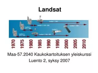
LANDSAT Series of Satellites NASA, with the co-operation of the U.S. Department of Interior, began a conceptual study of the feasibility of a series of Earth Resources Technology Satellites (ERTS). ERTS-1 was launched on July 23, 1972. It represented the first unmanned satellite specifically designed to acquire data about earth resources on a systematic, repetitive, medium resolution, multispectral basis. It was primarily designed as an experimental system to test that feasibility of collecting earth resources data from unmanned satellites. Just prior to the launch of ERTS-B on January 22nd 1975, NASA officially renamed the ERTS programme as "LANDSAT" programme. All subsequent satellites in the series carried the Landsat designation. So far five Landsat satellites have been launched successfully, Table highlights the characteristics of the Landsat series satellites mission. There have been four different types of sensors included in various combinations on these missions.
Multispectral Scanner (MSS) systems, Thematic Mapper (TM) and Enhanced Thematic Mapper (ETM). After more than two decades of success, the LANDSAT program realized its first unsuccessful mission with the launch failure of Landsat-6 on October 5, 1993. The sensor included on-board was the Enhanced Thematic Mapper (ETM). To provide continuity with Landsat -4 and -5 the ETM incorporated the same seven spectral bands and the same spatialresolutions as the TM. The ETM's major improvement over the TM was addition of an eighth panchromatic band operating in 0.50 to 0.90μm ranges a spatial resolution of 15m. Landsat-7 includes two sensors: the Enhanced Thematic Mapper plus (ETM+) and the High Resolution Multispectral Stereo Imager (HRMSI).
SPOT Series of Satellite French Government in joint programme with Sweden and Belgium undertook the development of Systeme Pour l'Observation de la Terre (SPOT) program. Conceived and designed by the French Centre National d'Etudes Spatiales (CNES), SPOT has developed into a large-scale international programme with ground receiving stations and data distribution outlets located in more than 30 countries. It is also the first system to have pointable optics. This enables side-to-side off-nadir viewing capabilities, and it affords full scene stereoscopic imaging from two different satellite tracks permitting coverage of the same area. SPOT-1 was retired from full-time services on December 31, 1990. The SPOT-2 satellite was launched on January 21, 1990, and SPOT-3 was launched on September 25, 1993 Spot 4 was launched on 26 March 1998. SPOT-1, -2 and -3 have identical orbits and sensor systems,
SPOT-4 includes the additional20m-resolution band in the mid-infrared portion of the spectrum (between 1.58 and 1.75μm). This band is intended to improve vegetation monitoring and mineral discriminating capabilities of the data. Furthermore, mixed 20m and 10m data sets will be co-registered on-board instead of during ground processing. This will be accomplished by replacing the panchromatic band of SPOT-1, -2 and -3 (0.49 to 0.73 μm) with red band from these systems (0.61 to 0.68 μm). This band will be used to produce both 10m black and white images and 20m multispectral data. Another change in SPOT-4 is the addition of a separate wide-field-of-view, sensor called the Vegetation SPOT-5 is the latest in France's series of Earth observing satellites, all of which were sent into orbit by Arianespace. Since the first SPOT satellite was launched in 1986, the SPOT system has sought to provide continuity of service and constantly improved quality of products for users. Spot 5 is the fifth satellite in the SPOT series, placed into orbit by an Ariane5 launcher in May 2002.
IRS Satellite Series The Indian Space programme has the goal of harnessing space technology for application in the areas of communications, broadcasting, meteorology and remote sensing. The important milestones crossed so far are Bhaskara-1 and 2 (1979) the experimental satellites, which carried TV Cameras and Microwave Radiometers. The Indian Remote Sensing Satellite was the next logical step towards the National operational satellites that directly generates resources information in a variety of application areas such as forestry, geology, agriculture and hydrology. IRS -1A/1B, carried Linear Self Scanning sensors LISS-I & LISS-II. IRS-P2 launched in October 1994 on PSLV-D2 (an indigenous launch vehicle). IRS-1C, launched on December 28, 1995, which carried improved sensors like LISS-III, WiFS, PAN Camera, etc. Details of IRS series platforms are given in the following section. IRS-P3 was launched into the sun synchronous orbit by another indigenous launch vehicle PSLV - D3 on 21.3.1996 from Indian launching station Sriharikota (SHAR). IRS-1D was launched on 29 September 1997 and IRS-P4 was launched on 26 May 1999.