Download
1 / 23
240 likes | 440 Vues
Fundamentals of Radio Astronomy. Lyle Hoffman, Lafayette College ALFALFA Undergraduate Workshop Union College, 2005 July 06. Outline. Sources in brief Radiotelescope components Radiotelescope characteristics. Useful Texts. Burke & Graham-Smith, An Introduction to Radio Astronomy

E N D
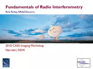
Fundamentals of Radio Astronomy Lyle Hoffman, Lafayette College ALFALFA Undergraduate Workshop Union College, 2005 July 06
Outline • Sources in brief • Radiotelescope components • Radiotelescope characteristics Useful Texts Burke & Graham-Smith, An Introduction to Radio Astronomy Rohlfs, Tools of Radio Astronomy Stanimirovic et al., Single-dish Radio Astronomy: Techniques and Applications
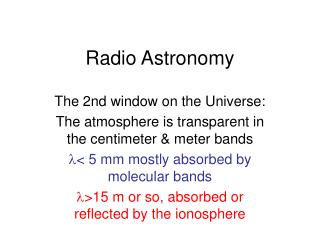
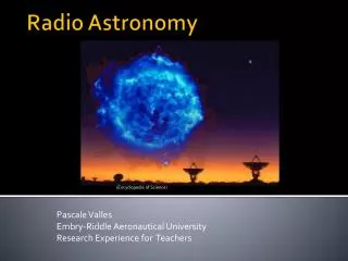
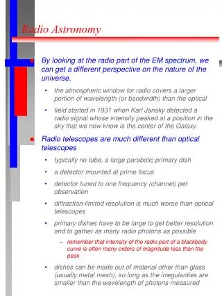
Sources of Radio Emission • Blackbody (thermal) • Continuum sources • Spectral line sources
Blackbody Sources • Peak in cm-wave radio requires very low temperature: lmT = 0.2898 cm K • Cosmic Microwave Background is about the only relevant blackbody source • Ignored in most work – essentially constant source of static (same in all directions) and much weaker than static produced by instrumentation itself
Continuum Sources • Due to relativistic electrons: Synchrotron radiation Bremsstrahlung • Quasars, Active Galactic Nuclei, Pulsars, Supernova Remnants, etc. • Used by ALFALFA for calibration
Spectral Line Sources • Neutral hydrogen (H I ) spin-flip transition • Recombination lines (between high-lying atomic states) • Molecular lines (CO, OH, etc.)
Doppler effect: frequency shift of spectral line due to relative motion of source and observer • Closely related: redshift due to expansion of universe • Customarily report “velocity” as cz = c(fo-f)/f
H I spectral line from galaxy shifted by expansion of universe (“recession velocity”) and broadened by rotation Frequency
Radiotelescope Components • Reflector(s) • Feed horn(s) • Low-noise amplifier • Filter • Downconverter • IF Amplifier • Spectrometer
Feedhorns Typical cm-wave feedhorn 4 GHz feedhorn on LCRT
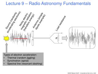
Signal Path Low-Noise Amplifier Down-converter Filter IF Amplifier Spectro-meter Local Oscil-lator
Autocorrelation Spectrometer • Special-purpose hardware computes autocorrelation function: Rn = N-1 S1N [u(tj)u(tj+ndt)] where dt is lag and u is signal voltage; integer n ranges from 0 to (dt df)-1 if frequency channels of width df are required • Power spectrum is discrete Fourier transform (FFT) of Rn
Nyquist theorem: must sample at rate 2B to achieve spectrum of bandwidth B without aliassing
Radiotelescope Characteristics • Gain & effective area • Beam, sidelobes, stray radiation • Sensitivity, noise & integration time • Polarization & Stoke’s parameters
Gain & effective area • Received power Prec • Flux (energy per unit area per unit time) S • Effective area Aeff = Prec / S • Gain G for transmitter is ratio of emitted flux in given direction to P/(4pr2) • Most emitted (received) within central diffraction max, angle ~ l / D • So G = 4p Aeff / l2
Beam & sidelobes • Essentially diffraction pattern of telescope functioning as transmitter • Uniformly illuminated circular aperture: central beam & sidelobe rings
Obstructions, non-uniform illumination by feedhorn asymmetry and alter strengths of sidelobes vs. central beam • Emission received from pattern outside first sidelobe ring often called stray radiation • FWHM of central beam is beamwidth • Integrated solid angle of central beam is Wo • Gain related to beam via G = 4p / Wo
Sensitivity • Limited by noise – mostly thermal noise within electronics but also from ground reflected off telescope structure into feedhorn and CMB • System temperature: temperature of blackbody producing same power as telescope + instrumentation produces when there is no source in beam
Often give brightness of source in temperature units: difference in effective blackbody temperature when source is in beam vs. when no source is in beam – even when source is spectral line or synchrotron radiation and brightness has little to do with actual temperature of the source • Preferred unit (requires calibration) is Jansky: 1Jy = 10-26 W m-2 Hz-1
Limiting sensitivity for unpolarized source set by requiring signal added by source to equal rms uncertainty in Tsys: DS = 2kTsys Aeff-1 (Bt)-1/2 (k: Boltzmann’s constant; t: integration time) • For spectral line work, B is set by velocity resolution required; Tsys and Aeff set by telescope and instumentation increase sensitivity by integrating longer – but need 4 times integration time to increase sensitivity by factor of 2
Polarization • H I sources unpolarized, but synchrotron sources are often polarized to some extent – E in plane of electron’s acceleration • Single receiver (LNA) can respond to only single polarization at any instant– either one component of linear polarization or one handedness of circular polarization • So two receivers required to receive both polarizations
Linear Ex and Ey with phase difference f • Stokes’ parameters: I = Ex2 + Ey2 Q = Ex2- Ey2 U = 2ExEycosf V = 2ExEysinf
Unpolarized source: Ex = Ey and f = 0 • So Q = 0, V = 0, and I = U for H I; usually report only Stokes’ I or total flux = sum of fluxes of x and y polarizations