Optimizing Collimator Design for ILC Wakefield Minimization
50 likes | 73 Vues
Collaborative project between Birmingham Univ, Manchester Univ, and more institutions aimed to design optimal ILC spoilers using Geant4 simulations. Results show Ti alloy with graphite being the best spoiler candidate. Studies extended to the ILC-BDS beamline with wakefield measurements at SLAC. Plans for 2007 include beam tests for material damage, wakefield simulations, and experimental tests at ESA. Particle Accelerator Conference abstracts for June 2007 in New Mexico.

Optimizing Collimator Design for ILC Wakefield Minimization
E N D
Presentation Transcript
Collimator design and short range wakefields Adriana Bungau Christmas meeting - 2006 Manchester
Collimator Design and Material Damage • Aim: design the optimal spoilers for the ILC ( geometry and material specification) • Project: collaboration between Birmingham Univ, Manchester Univ, Daresbury Laboratory, SLAC and RAL Geant4 simulations in Manchester • Collimator design - two types of spoilers: a full metal spoiler and a combinations of metal and graphite • Three materials used: Ti4Al6V, Copper, Aluminium • Beam was sent through the collimator at 2 depths: 2mm and 10 mm from the top • Decision of the best spoiler candidate was based on: - instantaneous temperature rise - outgoing particle multiplicities - energy spectra of outgoing particles • The best spoiler candidate was Ti alloy with graphite • Results were cross-checked with Fluka and EGS4 - passed on at RAL for ANSYS studies EUROTeV reports and EPAC papers: • Geant4 Simulations of Energy Deposition in ILC spoilers - A.Bungau, R.Barlow, N.Watson, EUROTeV Report-2006-021 • Shower simulations, comparison of FLUKA, GEANT4 and EGS4 - L.Fernandez, A.Bungau, L.Keller, R.Barlow, N.Watson, EUROTeV-Report-2006-034
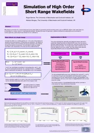
Wakefield simulations with Merlin • Current situation: • mathematical formalism for incorporating higher order mode wakefields (R.Barlow) • formalism implemented in the Merlin code • SLAC beam tests simulated (good agreement between analytical calculations and • experiment • so far, only simple beamlines were studied (ie. Drift, Collimator, Drift) EPAC paper: “Simulation of High Order Short Range Wakefields” - R.Barlow, A. Bungau, EUROTeV-Report-2006-051 Studies are now extended to the ILC-BDS beamline - emittance growth due to wakefields and luminosity loss
Wakefield Measurements at SLAC-ESA Motivation: to optimize the collimator design by studying various ways of minimising wakefield effects while achieving the required performance for halo removal • Collaboration between SLAC, Birmingham, Lancaster, Manchester, Daresbury • Commissioning: Jan 2006 (4 old collimators) - Successful • Physics: first run: Apr/May second run: July (8 new collimators – CCLRC) Experimental tests - tested 8 collimators fabricated at RAL - inserted collimators in beam path (x mover), moved collimator vertically (y mover),measured centroid kick to beam via BPMs - analysed kick angle vs collimator position (good runs as also bad runs) EUROTeV reports and EPAC papers: • "Test Beam Studies at SLAC End Station A for the International Linear Collider" -M.Woods et all,EUROTeV-Report-2006-060, SLAC-PUB-11988 • "Direct Measurement of Geometric and Resistive Wakefields in Tapered Collimators for the International Linear Collider" - N.Watson et all,EUROTeV-Report-2006-059, SLAC-PUB-12029
Plans for 2007 • Colimator damage: • beam tests for material damage (SLAC, CERN ?) • Wakefield simulations: • studies for the ILC_BDS collimators with higher order modes • implement Gdfidl predictions in Merlin • Experimental tests at ESA: • next run: March 2007 with 8 new collimators • BPM reprocessing on the Manchester cluster • data analysis finished for 2006 and also for 2007 • data comparison with the first 8 collimators used in 2006 • Particle Accelerator Conference, June 2007-New Mexico - 5 abstracts