Download
1 / 29
290 likes | 467 Vues
(1) LIMHP, CNRS-UPR 1311, Univeristé Paris 13, 99 Avenue J. B. Clément 93430 Villetaneuse, France (2) Department of Electrial Engineering, Michigan State University, USA East Lansing, USA (3) Dipartimento di Chimica – IMIP CNR Univeristy of Bari Italy. (4) INP Greifswald.

E N D
(1)LIMHP, CNRS-UPR 1311, Univeristé Paris 13, 99 Avenue J. B. Clément 93430 Villetaneuse, France (2)Department of Electrial Engineering, Michigan State University, USA East Lansing, USA (3) Dipartimento di Chimica – IMIP CNR Univeristy of Bari Italy (4) INP Greifswald Modeling of moderate pressure H2/CH4 microwave discharge used for diamond deposition K. Hassouni, F. Silva, G. Haagelar, X. Duten, G. Lombardi, A. Gicquel(1) T. A. Grotjohn(2) M. Capitelli(3) J. Röpcke(4)
Investigated Device : microwave cavity coupling system + belljar quartz vessel Usual Experimental Conditions : Feed Gas : H2/CH4 - %CH4 < 5 Pressure : 20-200 Torr Input Power : 0.4-4 kW Power density : 6-100 W/cm3 Flow Rates : 100 - 300 sccm Substrate Temperature : 1000 K - 1300 K Orders of magnitude : Plasma height 3.5 cm (for 2.45 GHz) Tg > 2000 K - 1011 cm-3 < ne <1013 cm-3
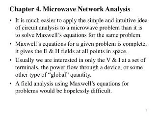
Wave-plasma interaction Electron heating Electron/heavy species collisions EEDF, <ee> e + A B Energy transfer, ionization, etc... VDF, Tv Tg Heavy species-heavy species collisions A B + , A , B ni, i=1-n Intermode energy transfer, chemistry Substrate (Ts, cs) Convection, Diffusion Energy and mass transport Plasma-surface interaction Mass and energy transfer Transport and collisional phenomena in the plasma (E,H) e A B ( v ) , A B ( r ) , A B Energy and mass transfer
What information do we need ? I. For a given coupling configuration, What’s the optimal reactor configuration that insures : 1- enhanced density of active species at the growing diamond film, 2- a good thermal stability of the reactor (during up to several weeks ) process engineering : mass and energy transport, gas phase and surface chemistry Strongly linked II. What is the optimal electromagnetic coupling conditions in term of : 1- power 2- pressure 2- frequency Electrical engineering : resonant electromagnetic modes, wave-plasma interaction
Modeling approach Detailed collisional model in moderate pressure H2 Plasmas * Determination of the main chemical processes and physical phenomena in the reactor. * Set up a satisfactory and useful Physical plasma model 2D Self-consistent model(Only for H2 discharges) Determine self consistent plasma, electomagnetic field and absorbed power distributions. for axisymmetrical configuration May be used for power deposition optimisation and for scaleup 1D transport model of the plasma on the stagnation line for both H2 and H2/CH4 discharges * Investigate the coupling between Chemistry, Energy Transfer and Transport Phenomena * Determine the behavior of the plasma temperatures and species.
Detailed Collisional model – H2 (1/2) I. Vibrational Kinetics Larichuta, Celiberto et al. * e- + H2(X,v) ==> e- + H2(X,w) |w-v| < 4 * e- + H2(X,v) ==> e- + H2(B1Su,v’) ===> e- + H2(X,w) * vv relaxation : H2(v) + H2(w) ===> H2(v1) + H2(w 1) * v-t exchange : H2(v) + H2 (or H) ===> H2(v1) + H2 (or H) * Dissociation from upper v by heavy species collisions: H2(v) + H2 (or H) ===> 2H + H2 (or H) II. Ground States Kinetics C. D. Scott et al. J. Thermophysics, Vol. 10 1996, p 426 * e- + H2(v=4-10) ==> H + H- * H2+ + H2 ==> H3+ + H * Recombination and mutual neutralization of ions For more detailed description : K. Hassouni, A. Gicquel, M. Capitelli and J. Loureiro Plasma source Science and Technology, 8(3), 494 (1999) .../..
Detailed Collisional model III. Electronically Excited States Kinetics : H2 and H Larichuta, Celiberto et al. H2 :K. Sawada et al. J. Appl. Phys., 78 (5), (1995), p. 2913 H :J. A. Kunc et al., Phys. Fluids, Vol. 30(7), (1987), p. 2255 * e- + H2(v) ==> e- + H2* and e- + H(n) ==> e- + H(m) * e- + H2 (v) = [H2**]=> H2+ + 2e- and e- + H(n) ==> 2e- + H+ * e- + H2 (v) = [H2**]=> 2H + e- * H2* + M ==> H2* or 2H * H(n) + H ==> H(m) + H * M* ==> M*’ + hn (M=H or H2) Optically thick plasma for Lyman radiations M. Glass-Maujean Phys. Rev. Lett., Vol. 62 (2), (1989), p. 144 H(n=2) + H2 ==> H3+ + e- (s = 15-30 A2) H(n>2) + H2 ==> H3+ + e- - Assumption in this work - For more detailed description : K. Hassouni, A. Gicquel, M. Capitelli ad J. Loureiro Plasma source Science and Technology, 8(3), 494 (1999)
D a t a d d w M W P , P , , i n p t s , / N I n i t i a l G u e s s E / N , P l a s m a c o m p o s i t i o n , T g ) p n i P E l e c t r o n B o l t z m a n n E q u a t i o n W T w o t e r m e x p a n s i o n M - n E E D F , R a t e C o n s t a n t s , c e - s P W M C a l c u l a t e t h e t r a n s p o r t C o e f f i c i e n t s ( o t S p e c i e s a n d e n e r g y L o s s e s a t t h e w a l l g n i d r S p e c i e s k i n e t i c s E q u a t i o n s o c c a N e w P l a s m a c o m p o s i t i o n N / E t T o t a l E n e r g y E q u a t i o n c e r r N e w T g o C C a l c u l a t e t h e n e w a b s o r b e d M W p o w e r No Y e s e | M W P c - M W P i n p | < T g , E / N , E E D F , V D F a n d S p e c i e s d e n s i t i e s Use of the detailed kinetics in the frame of Quasi-homogeneous plasma model Simulation procedure Use the effective field assumption => stationary situation EEDF VDF H2*(n=1-36) H*(n=1-40) H+, H2+, H3+, H-, e- Tg
0 5 10 15 20 25 30 Quasi-homogenous plasma model Most significant results : vibrational distribution/ 102 Exc. Vib. 101 Exc. trans-rot. 100 Dissociation Densité de puissance dissipée (W/cm3) Exc. Elec. H2 10-1 Exc. Elec. H 10-2 10-3 MWPDav (W/cm3)
1E+00 1E-02 T = 19200 K e-l 1E-04 1E-06 FDEE (eV-3/2) T = 8500 K 1E-08 e-h 1E-10 1E-12 0 5 10 15 20 25 ee(eV) Quasi-homogenous plasma model : most significant results EEDF behavior and electron impact rate constants rate constants of Electron-impact process H2 dissociation Bimodal distribution FDEE Bimodale Te-h = f(Te-l) (univoque) Energy balance Te-l Te-h Rate constants only depend on Te-l We can use a scalar model to describe the electron kinetics
108 2 3 10-1 4 106 H(n=2-3) + H2 => H3+ + e- 5 6 104 10-2 e-+H2 => 2e- + H2+ H2+ + H2 => H3+ + e- ionisation rate (mol. m-3.s-1) 102 Densité(cm-3) 10-3 9.0 W/cm3 100 e-+H => 2e- + H+ 30.0 W/cm3 10-2 10-4 20 10 15 20 25 30 35 MWPDav (W/cm3) 10-4 10 11 12 13 14 En (eV) Quasi-homogenous plasma model Most significant results Ionization kinetics & H-atom excited states kinetics 100 Main ionization channel : quenching of H(n=3) and H(n=2) states • Excited state distribution • coupling between excited levels H* • H(n=2-3) kinetics do not depend on H(n>3) states
12 1x10 0.2 Simplified model 11 0.18 9x10 0.16 11 8x10 ) 0.14 -3 11 7x10 0.12 H-atom Relative density 11 6x10 Electron density (cm 0.1 11 5x10 0.08 11 0.06 4x10 0.04 11 3x10 0.02 Detailed model 11 2x10 0 11 1x10 0 10 20 30 40 0 5 10 15 20 25 30 35 Power density (W/cm^3) 3 MWPD (W/cm ) av Quasi-homogenous plasma model Most significant results From full model to simplified model : 9 species [H2,H,H(n=2),H(n=3),H+,H2+,H3+, e-] /2 energy modes [Tg, eedf] Simplified model Detailed model
2D Self-consistent model for moderate pressure plasma flow EM field simulation domain 2 Modules A plasma module simulates the discharge in the low pressure vessel An electromagnetic module simulates the EM field in the whole cavity Plasma simulation domain Hassouni, Grotjohn and Gicquel, J. Appl. Phys.(1999) Hagelaar, Hassouni and Gicquel, J. Appl. Phys. (2004)
Ee + div(uehe-leTe) –PEM + Qe-t + Qe-v + Qe-C =0 t Ev-m E + div[Suihi –lt-rT-Slv-mTv-m –leTe] - PEM + Qrad = 0 + div(umEv-m-lv-mTv-m) + Qv-t - Qe-v + Qv-C = 0 t t ¶ n => ( ) => + + Ñ × - Ñ - = D n W 0 i u n i i i ¶ t i Plasma module 2 or 3-temperature thermo-chemically non-equilibrium flow models Continuity => species density Navie-Stockes => Flow velocity Electron energy => Te EM module H2-vibration mode => Tv Total energy => Tg EM module Coupling nodes
¶ E Ñ ´ = + e H J HF 0 ¶ t = - J q n v HF e e HF plasma model d v = - - u m HF q E m v e e eff HF dt Electromagnetic module A time-domain model where the plasma is considered as a high frequency conductor Maxwell Curl equations Momentum equation for the HF component of the electron flow velocity plasma model Hassouni, Grotjohn and Gicquel, J. Appl. Phys.(1999) Hagelaar, Hassouni and Gicquel, J. Appl. Phys. (2004)
Er(i+1/2,j+1,k) Hr(i,j+1/2,k+1/2) Hf(i+1/2,j,k+1/2) Ez(i,j,k+1/2) Ez(i+1,j,k+1/2) Hz(i+1,j+1/2,k) Ef(i,j +1/2,k) Er(i+1/2,j,k) 2D Self-consistent model for moderate pressure plasma flow Numerical method : Finite Difference Time Domain Method Explicit time integration Leap-Frog shift between E and H, to acheive second order accuracy • Staggered grids for the different components of E and H Are naturally satisfied at the grid points • Only TM modes are considered in this calculation 2 kinds of boundary conditions are used : Perfect conductor: Et=0 and Hp=0 Nonreflecting boundary condition at the cavity inlet Define an excitation plane in the computation domain
Grid interpolation Te, Tg, ne Electromagnetic module Maxwell Curl equations HF Momentum equation for electrons E, H, Je-HF, MWPD 15-25 microwave periods Plasma model 12 Transport equations 9 espèces -Tg, Tv, <ee> 300-400 iterations 15-20 Iterations Microwave power density Grid interpolation 2D Self-consistent model Iteration scheme Simulation procedure wp, nQ-M ep E.Je-HF
Validation of the electromagnetic module Electric field intensity in the cavity Self consistent model without plasma CST Microwave Studio (Commercial code)
Tg(K) 18 W/cm3 2000 K Te(K) ne(K) 4x1011 cm-3 20000 K Some results : 600 W – 25 mbar MWPDav=8W/cm-3 Power density (W.cm-3)
Optimal power deposition at 50 mbar ne nH Tg ||E|| 1 ball regime MWPinp↗ Vplasma ↗ then MWPinp Transition 1B to 2B 500 W 600 K Gas heating is responsible for Discharge regime transition Ignition for maximum E/N Tg ↗ E/N distribution changes 800 W 1200 K Very similar to some explenation given for streamer to arc transition phenomenon 1000 W
2D-self consistent model Flow effect at high power density With free convection Strong free convection Without free convection Inlet
dV d dV r du u d é ù æ ö et ê ú 2 r u + r V - m + L =0 + 2V + =0 ç ÷ ê ú dz dz dz dz dz r è ø ë û d M q dT dx d M é æ ö ù æ ö ê ú s k g s s + - Ws =0 r D - r u x ç ÷ ç ÷ ê ú dz M T dz dz s dz M s è ø è ø ë û g 2 d< e > d 2 d< e > æ ö e e + r c (u + u ) - l ç ÷ 3k dz dz 3k dz e p-e e e è ø 1D transport model for H2 plasma flow • 2 Momentum Equations => V=dv/dr|r=0 and u Radial uniformity Simulation Domain • continuity equations for species : Substrate • 2 energy equations : Tg, Te-l - MWPD + Qe-v + Qe-t + Qe-C = 0 2D SC model
1D transport model for H2/CH4 plasma flow 31 species - 134 reactions model Three reactions Groups H2/CH4 (Thermal Hydrocraking : C1-2H1-6 species) : * B. W. Yu and S. L. Girshick, J. Appl. Phys., 75(8), 1994, p. 3914 * C. T. Bowman et al., http://www.me.berkley.edu/gri_mech/ Pressure correction on three body recombination reaction • CxHy Charged species kinetics : • Ionization kinetics : e- + CxHy ==> 2e- + CxHy+ • H.Tawara et al., Research Report NIFS-DATA, • Charge transfer kinetics : H3+ + CxHy ==> H2 + CxHy+1+ • * H. Tahara et al., Jpn. J. Appl. Phys., 34. • * Dissociative Recombination : CxHy+ + e- ==> CxHy-1 + H • Lahfaoui et al. J. Chem. Phys., 106 (13)
1D transport model for H2 plasma flow Some results Comparison with experiments MWPD = 9 W/cm -3 (MWPinp = 600 W and P = 25 mbar) Conclusion : * Good Agreement on temperatures * H-atom is overestimated in the boundary layer ( 50 %)
Radiale Uniformity Substrate • Temperature 3500 -3 30 W.cm -3 9 W.cm 3000 -3 12 W.cm -3 15 W.cm 2500 -3 23 W.cm -3 30 W.cm Gas temperature [K] 2000 -3 9 W.cm 1500 (a) 1000 0 1 2 3 4 5 6 7 8 9 10 Axial position [cm] Axial profiles of temperature and hydrogen mole fraction simulation domain • H-atom 1/ H-atom relative density varies between 1 et 13 % when MWP 9 à 30 W.cm-3 2/ The discharge transitions from a cold non-equilibrium plasma to a thermal plasma
Axial distribution of hydrocarbon species30 W.cm-3 (120 mbar / 2 kW) CHx C2Hy Tgmax = 3200 K 1/ C2H2 is the major species (Actually we have H2/C2H2 plasma) 2/ Strong density variations in the reacting boundary layer (spatial stiffness) 3/ Significant amount of C and C2 species 4/ Caution : Interpretation of line of sight measurements outside or inside the discharge ?
60 cm Tg~3000 K 2 cm Tg=300 K Bras optique 0 Tg=600 K 10 5 cm 25 cm 2.5 cm -1 10 C H -2 2 2 10 CH -3 10 4 -4 10 CH3 Fraction molaire -5 10 CH 4 CH -6 C2H6 10 C H 3 C H 2 4 -7 10 2 2 C H 2 4 -8 10 C H 2 6 -9 10 -10 10 0 5 10 15 20 25 30 Position radiale [cm] Example : validation of predicted hydrocarbon species densities TDLAS measurements (INP : Greifswald – J. Ropcke) • Absorption measurements yield : • => CH3 in the discharge • C2H6 outside the discharge • The model allows to get the spatial distribution • and the validation takes place on spatially averaged values C2H6 CH3
1D transport model for H2/CH4 plasma flow Comparison with IR absorption measurements Low power density – 9 W/cm-3 High power density – 30 W/cm-3 C2H2+ : e-+C2H2 => 2e- + C2H2+ e-+ C2H2+ => C2H + H CH4 + C2H2+ => C2H3+ + CH3 C2H3+ : CH4 + C2H2+ => C2H3+ + CH3 H3+ + C2H2 => C2H3+ + H e-+ C2H3+ => C2H2 + H C2H2+ : e-+C2H2 => 2e- + C2H2+ e-+ C2H2+ => C2H + H C2H3+ : H3+ + C2H2 => C2H3+ + H e-+ C2H3+ => C2H2 + H C2H5+ : C2H4 + C2H3+ => C2H5+ + C2H2 e-+ C2H5+ => C2H4 + H C2H5+ : C2H4 + C2H3+ => C2H5+ + C2H2 e-+ C2H5+ => C2H4 + H
Open problems in H/C moderate pressure microwave discharges for carbon films deposition Soot • Treatment of more complex discharges …. • Sooting discharges for nano and ultranano-crystalline diamond deposition (PAH and soot formation) – undergoing work • Self consistent treatment of pulsed regime – undergoing work • Electron velocity distribution function : anisotropy effect (nel wexc) • EM field simulation : Resonance region and spatial stiffness • More detailed investigation of the effect of gas heating on the establishment of discharge regimes