Fluoroscopic Image Display
Fluoroscopic Image Display. Television Cameras. 3 Methods: Thermionic television camera tube Solid state charge-coupled device (CCD) Active pixel sensors (APSs) or (CMOS) Coupling I.I. to TV tube, CCD or APS Fiber optics. Video Viewing System. Closed circuit television

Fluoroscopic Image Display
E N D
Presentation Transcript
Television Cameras • 3 Methods: • Thermionic television camera tube • Solid state charge-coupled device (CCD) • Active pixel sensors (APSs) or (CMOS) • Coupling I.I. to TV tube, CCD or APS • Fiber optics
Video Viewing System • Closed circuit television • Video camera coupled to output screen and monitor • Video cameras • Vidicon or Plumbicon tube • CCD • APS
Viewing The output phosphor of the II is connected by fiber optic cables directly to a TV camera tube when the viewing is done through a television monitor. The most commonly used camera tube - vidicon Inside the glass envelope that surrounds the TV camera tube is a cathode, an electron gun, grids and a target. Past the target is a signal plate that sends the signal from the camera tube to the external video device
Type of TV camera • VIDICON TV camera • improvement of contrast • improvement of signal to noise ratio • high image lag • PLUMBICON TV camera (suitable for cardiology) • lower image lag (follow up of organ motions) • higher quantum noise level • CCD TV camera (digital fluoroscopy) • digital fluoroscopy spot films are limited in resolution, since they depend on the TV camera (no better than about 2 lp/mm) for a 1000 line TV system
Camera tube have a diameter of approximately 1 inch and a length of 6 inches.
Parts of the camera tube • Glass envelope • Electron gun (Cathode) • Control grid • Electrostatic grids • Target
Camera Tube steps • Light is received by the camera tube. • The light from the II is received at the face plate of the target assembly. • Electrons are formed into an electron beam (by the control grid) at the electron gun. • Electrons are burned off by thermionic emission then focused and accelerated to the target. (made of antimony trisulfide)
The electrons scan the signal plate similar to reading a page. • Starting in the upper left across to the right, then back to the left to right. • This is called an active trace. • The movement of the electron beam produces a RASTER pattern. • The same pattern occurs in the TV monitor.
The signal plate sends the electrical video signal to the control unit which amplifies the signal and synchronizes the pulses between the camera tube and the TV monitor. • TV tube and monitor must be synchronized and duplicated to build a coherent image.
Charge-Coupled Devices (CCDs) Each electrode is connected to a storage capacitor (TFT) • 1980s CCD were developed and replaced TV tubes and miniaturized imaging devices. • Light photons enter the silicon layer, ionization of the light separates the e-. A layer of microscopic electrodes beneath the silicon acts as a ground for the freed electrons. Movement of charges can be measured by a circuit.
Video Camera Charged Coupled Devices (CCD) • Operate at lower voltages than video tubes • More durable than video tubes • Semiconducting device • Emits electrons in proportion to amount of light striking photoelectric cathode • Fast discharge eliminates lag
Advantages of CCDs • High spatial resolution • High SNR • High DQE • No spatial distortion • Unlimited life • Linear response to radiation • Lower patient dose • Wider dynamic range and better contrast resolution than conventional fluoroscopy
TV camera and video signal (V) • On most fluoroscopy units, the resolution of the system is governed by the number of lines of the television system. MTF • Thus, it is possible to improve the high contrast resolution by increasing the number of television lines. • Some systems have 1,000 lines and prototype systems with 2,000 lines are being developed. • Color TV requires 3 vidicon tubes for each of the wavelengths (red, green, and blue)
Monitors • Cathode ray tube (CRT) • Liquid crystal display (LCD) Active matrix liquid crystal display • Emissive displays = produce their own light (diodes) Not found application for medical imaging so far. • Plasma screen • Light-emitting diode (LED)
MONITOR • CRT – Cathode Ray Tube • Much larger than camera tube – but similar function • The electrons are synchronized by the control unit – so they are of the same intensity and location as the electrons generated by the pick up (camera) tube.
TV Monitor • The TV monitor contains the picture tube called cathode ray tube (CRT). • It works like the camera tube. • With an electron gun and control grids the electron beam is fired toward the anode. • The TV screen contains small fluorescent crystals
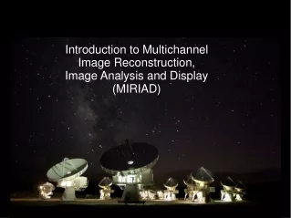
Different types of scanning 11 1 INTERLACED SCANNING 13 12 3 2 15 14 625 lines in 40 ms i.e. : 25 frames/s 5 4 17 16 7 6 19 18 9 8 21 20 10 1 2 3 4 5 6 7 PROGRESSIVE SCANNING 8 9 10 11 12 13 14 15 16 17 18
Two fields = a frame (525 lines) • It take 1/30 of a second. • To prevent flicker, two fields are interlaced to form on television frame. • There are 60 fields and 30 frames per second. Each frame takes 33 ms to form • The eye cannot detect flickering above 20 frames/sec.
RASTER Pattern • The electron beam moves in the same raster pattern as in the camera tube. • The signal consists of many individual pulses corresponding to the individual location on the camera tube target. • The varying voltage pulses are later reassembled into a visible in by the TV monitor.
Refresh rate • The refresh rate is the measure of how fast the monitor rewrites the screen or the number of times that the image is redrawn on the display each second. The refresh rate helps to control the flicker seen by the user; the higher the refresh rate, the less flicker.
TV RESOLUTION-Vertical • Conventional TV: 525 TV lines to represent entire image. Example: 9” intensifier (9” FOV) • 9” = 229 mm • 525 TV lines/229 mm = 2.3 lines/mm • Need 2 TV lines per test pattern line-pair • (2.3 lines/mm) /2 lines/line-pair = 1.15 lp/mm • Actual resolution less because test pattern bars don’t line up with TV lines. Effective resolution obtained by applying a Kell Factor of 0.7. Example: 1.15 x 0.7 Kell Factor = 0.8 lp/mm
Kell Factor • The ability to resolve objects spaced apart in a vertical direction. • More dots = more scan lines = more/better resolution • Kell factor for 525 line system is 0.7
VERTICAL RESOLUTION ABILITY TO RESOLVE OBJECTS SPACED APART IN A VERTICAL DIRECTION MORE DOTS(GLOBULES) = MORE SCAN LINES = MORE/BETTER RESOLUTION RATIO OF VERTICAL RESOLUITON # OF SCAN LINES KELL FACTOR FOR 525 LINE SYSTEM IS 0.7 KELL FACTOR
Dot pitch • Dot pitch is the measurement of how close the dots are located to one another within a pixel
TV RESOLUTION-Horizontal • Along a TV line, resolution is limited by how fast the camera electronic signal and monitor’s electron beam intensity can change from minimum to maximum. • This is bandwidth. For similar horizontal and vertical resolution, need 525 changes (262 full cycles) per line. Example (at 30 frames/second): 262 cycles/line x 525 lines/frame x 30 frames/second = 4.2 million cycles/second or 4.2 Megahertz (MHz)
Bandpass/Horizantal Resolution • Horizontal resolution is determined by the bandpass. • Bandpass is expressed in frequency (Hz) and describes the number of times per second the electron beam can be modulated. • The higher the bandpass, the better the resolution
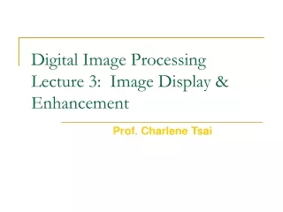
Different types of scanning 11 1 INTERLACED SCANNING 13 12 3 2 15 14 625 lines in 40 ms i.e. : 25 frames/s 5 4 17 16 7 6 19 18 9 8 21 20 10 1 2 3 4 5 6 PROGRESSIVE SCANNING USED IN DIGITAL 7 8 9 10 11 12 13 14 15 16 17 18
Digital Uses Progressive Scan • 1024 x 1024 • Higher spatial resolution • As compared to 525 • 8 images/sec • (compared to 30 in 525 system)
Digital Uses Progressive Scan • SNR for TV camera tubes 200:1 • SNR necessary for DF Is 1000:1 • Each image takes 33 ms To display
TV SYSTEMS • Images are displayed on the monitor as individual frames – which tricks the eye into thinking the image is in motion (motion integration) • 15 f/sec – eye can still see previous image • Weakest Link - 2 lp/mm resolution • Real Time
Final Image • The result of hundreds of thousands of tiny dots of varying degrees of brightness. • These dots are arranged in a specific patterns along horizontal scan lines. • Usually 525 scan lines. • The electron gun within the picture tube scans from top to bottom in 1/60 of a second, (262 1/2 lines) called a field.
Bandpass/Horizontal Resolution • Horizontal resolution is determined by the bandpass. • Bandpass is expressed in frequency (Hz) and describes the number of times per second the electron beam can be modulated. • The higher the bandpass, the better the resolution
TV RESOLUTION-Horizontal • Along a TV line, resolution is limited by how fast the camera electronic signal and monitor’s electron beam intensity can change from minimum to maximum. • This is bandwidth. For similar horiz and vertical resolution, need 525 changes (262 full cycles) per line. Example (at 30 frames/second): 262 cycles/line x 525 lines/frame x 30 frames/second = 4.2 million cycles/second or 4.2 Megahertz (MHz)
active matrix liquid crystal display (AMLCD) • Must have sharper resolution and high speed, each pixel has its own TFT
Nematic liquid crystals • Light is twisted along with the crystals. Varying the amount of twisting vs alignment allows for more or less light and greys in between.