Download
1 / 32
360 likes | 810 Vues
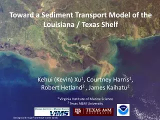
Development of a DHSVM Erosion and Sediment Transport Model. Presented by Jordan S. Lanini, University of Washington.

E N D
Development of a DHSVM Erosion and Sediment Transport Model Presented by Jordan S. Lanini, University of Washington Colleen O. Doten, University of WashingtonLaura C. Bowling, Purdue UniversityEdwin D. Mauer, Santa Clara UniversityJordan S. Lanini, University of Washington Nathalie Voisin, University of WashingtonDennis P. Lettenmaier, University of Washington
Presentation outline • Motivation for erosion model • Mass wasting component • Surface erosion component • Channel erosion and routing component • Testing and evaluation • Future research directions
Motivation for erosion model Forest Roads www.homefirefightingsystems.com Forest Fire Timber Harvest
SURFACE EROSION DHSVM Qsed Q OUTPUT MASS WASTING Sediment Model CHANNEL EROSION & ROUTING Provides Inputs for all Three Components Watershed Sediment Module Watershed Sediment Module
DHSVM CHANNEL EROSION & ROUTING MASS WASTING SURFACE EROSION DHSVM Inputs to Sediment Model Soil Moisture Content Channel Flow Precipitation Leaf Drip Infiltration and Saturation Excess Runoff
Mass Wasting http://www.for.gov.bc.ca/research/becweb/zone-MH/mh-photos/
Dynamic soil saturation predicted by DHSVM • Finer resolution grid (10 m) for failure computation Icicle Creek, WA L. Bowling, C. Doten
Mass Wasting Module (MWM) • Slope stability is a function of soil moisture, slope, and soil and vegetation characteristics. • Failure is determined by the infinite slope stability model, using a factor of safety (FS) resisting forces driving forces FS = • Slope instability is indicated by a FS < 1. L. Bowling, C. Doten
MWM - Stochastic Nature • Four soil and vegetation characteristics: • soil cohesion, • angle of internal friction, • root cohesion, and • vegetation surcharge are input as probability distributions. • They can be assigned to one of three distributions: • uniform, • normal or • triangular. L. Bowling
Results of a Stochastic Run Probability of failure Pixels in black failed at least once in 1000 iterations of MWM L. Bowling
MWM - Mass Redistribution • Pixels are considered to fail to bedrock. • Failed material travels down the slope of steepest descent. • Downslope pixels can fail in response to the initial failure. • Landslide stops at a critical slope angle. The failed volume is evenly distributed among all downslope pixels. • Landslides entering channels system continue as debris flows depending on the junction angle. L. Bowling
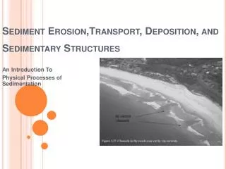
Surface Erosion & Routing http:www.geo.uni-bonn.de/cgi-bin/geodynamik_main?Rubrik=research&Punkt=geomorphology
Current DHSVM Runoff Generation and Routing Runoff is produced via: • Saturation excess (pixels 6 and 7) • Infiltration excess based on a user-specified static maximum infiltration capacity (pixel 3) Runoff is routed to the downslope neighbors one pixel/time step
Runoff Generation – Dynamic Infiltration Excess • Calculation of maximum infiltration capacity: • The first timestep there is surface water on the pixel, all surface water infiltrates. • If there is surface water in the next timestep, the maximum infiltration capacity is calculated based on the amount previously infiltrated. • Dominant form of runoff generation on unpaved roads and post burn land surfaces N. Voisin
Kinematic Runoff Routing • Pixel to pixel overland flow routed using an explicit finite difference solution of the kinematic wave approximation to the Saint-Venant equations • Manning’s equation is used to solve for flow area in terms of discharge • Per DHSVM timestep, a new solution sub-timestep is calculated satisfying the Courant condition, which is necessary for solution stability. L. Bowling
Surface Erosion • Transportable sediment is the sum of particles detached by three mechanisms • Erosion is limited by overland flow transport capacity raindrop impact leaf drip impact shearing by overland flow Mechanisms of Soil Particle Detachment L. Bowling, J. Lanini, N. Voisin
Hillslope Sediment Routing • Sediment is routed using a four-point finite difference solution of the two-dimensional conservation of mass equation. • If the pixel contains achannel (including road side ditches), all sediment and water enters the channelsegment. sediment and water L. Bowling
Forest Road Erosion • Transportable sediment consists of particles detached by two mechanisms • Overland flow will be infiltration excess generated. • Routing to include road crown type • insloped • outsloped • crowned surface erosion raindrop impact shearing by overland flow C. Doten
Channel Erosion & Routing www.eas.purdue.edu/geomorph/ envben.html
Channel Routing • Sediment Supply • channel sediment storage from the MWM • lateral inflow from hillslope and roads • upstream channel segment • Sediment particles • have a constant lognormally distributed grain size which is a function of the user-specified median grain size diameter (d50)and d90 • are binned into a user-specified number of grain size classes E. Maurer
Channel Routing • Sediment is routed using a four-point finite difference solution of the two-dimensional conservation of mass equation. • Instantaneous upstream and downstream flow rates are used in the routing. • Transport depends on • available sediment in each grain size class, and • capacity of flow for each grain size calculated using Bagnold’s approach for total sediment load. E. Maurer
Testing and Evaluation Little Wenatchee
Soil depth typically a hydrologic calibration parameter changes in soil depth will impact mass wasting Soil moisture mass wasting model uses soil moisture in each pixel at a daily time step unrealistic degrees of saturation are going to effect mass wasting MWM Application Challenges C. Doten
Model resolution smaller resolutions will result in smaller sub-time step, increasing run time Runoff (Infiltration Excess) Sub-timestep calculated from largest infiltration excess observed for time step unrealistic values will result in smaller sub-time step, increasing run time Surface erosion run time since mass wasting is the predominant form of sediment transport in PNW basin, surface erosion can be limited to user-specified time periods decreasing run time Surface Erosion Application Challenges C. Doten, J. Lanini
Mass wasting Land slide mapping of Rainy Creek derived from aerial photography Surface erosion Observed local and regional land and road surface erosion rates Channel routing Observed stream sediment concentrations Testing and Evaluation C. Doten
Scenario Analyses I: Forest Roads Forest Road Erosion Road Location in the Hillslope & Hillslope Curvature C. Doten
Scenario Analyses II: Timber Harvest and Forest Fire Enhanced Transport Capacity • Decrease in annual evaporation • Increased snow accumulation • Enhanced snow melt • Greater radiation exposure • Increased turbulent energy transfer Enhanced Sediment Supply • Mass wasting (landslides) • Decreased root strength • Enhanced soil moisture • Surface erosion http://www.for.gov.bc.ca/research/becweb/zone-MH/12_Res_Man.htm C. Doten
Questions/Comments We would like to acknowledge financial support from the USFS PNW Research Station and Wenatchee Lab for the development of this model
Data Input Needed for Sediment Model • Smaller resolution (10m) DEM • Debris Flow Material d50 and d90 • Soils: Bulk Density, Manning n, K index, d50, distributions (mean, stand deviation, minimum value, maximum value) of Cohesion and Angle of Internal Friction • Vegetation: Vegetation Surcharge distribution (minimum value and maximum value) and Root Cohesion distribution (mode, minimum value and maximum value)
References • Bagnold, R.A., 1966, An approach of sediment transport model from general physics. US Geol. Survey Prof. Paper 422-J. • Benda, L. and T. Dunne, 1997, Stochastic forcing of sediment supply to channel networks from landsliding and debris flow, Wat. Resour. Res, 33 (12), 2849-2863. • Beven, K.J. and M.J. Kirkby, 1979, A physically based, variable contributing area model of basin hydrology, Hydrol Sci Bull, 24, 43-69. • Burton, A. and J.C. Bathurst, 1998, Physically based modeling of shallow landslide sediment yield at a catchment scale, Environmental Geology, 35 (2-3). • Chow V.T., D.R. Maidment, L.W.Mays 1988: Applied Hydrology. McGraw-Hill Book Company pp572. • Epema G.F., H. Th. Riezebos 1983: Fall Velocity of waterdrops at different heights as a factor influencing erosivity of simulated rain. Rainfall simulation, Runoff and Soil Erosion. Catena suppl. 4, Braunschweig. Jan de Ploey (Ed). • Everaert, W., 1991, Empirical relations for the sediment transport capacity of interill flow, Earth Surface Processes and Landforms, 16, 513-532. • Exner, F. M., 1925, Über die wechselwirkung zwischen wasser und geschiebe in flüssen, Sitzungber. Acad. Wissenscaften Wien Math. Naturwiss. Abt. 2a, 134, 165–180. • Graf, W., 1971, Hydraulics of Sediment Transport, McGraw-Hill, NY, NY, pp. 208-211. • Grayson R.B., Blöschl G. and I.D. Moore : Distributed parameter hydrologic modeling using vector elevation data: THALES and TAPES-C. Chapter 19 in: Computer Models of Watershed Hydrology, Water Resources Publication, Highland Ranch, Colorado. p669-696. • Hammond, C., D. Hall, S. Miller and P. Swetik, 1992, Level I Stability Analysis (LISA) Documentation for version 2.0, USDA Intermoutain Research Station, General Technical Report INT-285.
References (con’t) • Komura, W., 1961, Bulk properties of river sediments and its application to sediment hydraulics, Proc. Jap. Nat. Cong. For Appl. Mech. • Morgan, R.P.C., J.N. Qinton, R.E. Smith, G. Govers, J.W.A. Poesen, K. Auerswald, G. Chisci, D. Torri and M.E. Styczen, 1998, The European soil erosion model (EUROSEM): a dynamic approach for predicting sediment transport from fields and small catchments, Earth Surface Processes and Landforms, 23, 527-544. • Rubey, W.W., 1933, Settling velocities of gravels, sands, and silt particles, Am. Journal of Science, 5th Series, 25 (148), 325-338. • Shields, A., 1936, Application of similarity principles and turbulence research to bedload movement. Hydrodynamic Lab. Rep. 167, California Institute of Technology, Pasadena, Calif. • Smith R.E. and J.Y. Parlange 1978: A parameter-efficient hydrologic infiltration model. Wat. Resour. Res. 14(3), 533-538. • Smith R.E., D.C. Goodrich, D.A. Woolhiser, and C.L. Unkrich 1995: KINEROS – a kinematic runoff and erosion model. Chapter 20 in: Computer Models of Watershed Hydrology, Water Resources Publication, Highland Ranch, Colorado. p697-732. • Sturm, T., 2001, Open Channel Hydraulics, McGraw-Hill, NY, NY, pp. 378-380. • Wicks, J.M. and J.C. Bathurst, 1996, SHESED: a physically based, distributed erosion and sediment yield component for the SHE hydrological modeling system, Journal of Hydrology, 175, 213-238. • Wigmosta, M.S., and D.P. Lettenmaier, 1999, A Comparison of Simplified Methods for Routing Topographically-Driven Subsurface Flow, Wat. Resour. Res., 35, 255-264. • Wolohiser, D.A., R.E. Smith and D.C. Goodrich, 1990, KINEROS, A kinematic runoff and erosion model: documentation and user manual, USDA-Agricultural Research Service, ARS-77, 130 pp.