Download
1 / 32
320 likes | 457 Vues
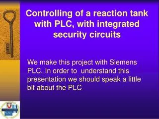
Controlling of a reaction tank with PLC, with integrated security circuits. We make this project with Si e mens PLC. In order to understand this presentation we should speak a little bit about the PLC. PLC (Programable Logic Controller). PLC software type: Graphic (LAD)

E N D
Controlling of a reaction tank with PLC, with integrated security circuits We make this project with Siemens PLC. In order to understand this presentation we should speak a little bit about the PLC
PLC(Programable Logic Controller) PLC software type: Graphic (LAD) Logical Symbolum (FBD) Programming of instructions (STL)
Usually we use the Graphic (LAD) because this is used frequently • The PLC circuit needs conditions and connections. • The AND connection • If both the 2 conditions are possible, there will be sign on the output. For example in a factory when we want to start a machine we must push two switches at the same time, because of security reasons.
The OR connection: • If one of the conditions is possible, there will be sign on the output. • For example we want to turn on a light which has got two switchers.
Self-control Connection • If both I0.0 and I0.1 possible There will be sign on the output until I0.2 doesn’t work • For example if I want to start a machine with a button, it will work until I keep pushing it. But if we use a self-control connection it will work until I want it.
Controlling of a reaction tank with PLC, with integrated security circuits
Filling pre-loader tank 1 The filling of the pre-loader tank will start by pressing a button, but only if the tank is empty (so the two level sensors are in standby) and the depletion is not switched on. If the tank is being filled it will be stopped by the upper level’s sensor.
Filling pre-loader tank 2 It is the same as the operation of the first tank
Depletion of pre-loader 1 The technician will start the procedure by pressing a button, but it is only available when the valve of the filling-tank is not switched on, and the second tank is full (because of security reasons).
Depletion of pre-loader 2 The technician can deplete the tank in order to clean it.
The mixing engine Both the minimal level of the reaction tank and the start button are to start the engine mixing.
The safety levels • Tmax (70°C) ->Normal level • Ttúl (75°C) ->Over-heated level • Tvész (80°C) ->Critical level The heating levels must be adjusted to the real technology. These values are just examples, they are not real.
Tmax - First safety level The heating process is on. It works automatically. If the temperature reaches Tmax, the three-way valve will turn off the heating. You can see it in the next picture (first safety level). Tmax
Ttúl - Second safety level If the temperature reaches Ttúl (Over-heated level), it will turn on the cooling. The emergency light will turn on, too. See it on the next page (second safety level) Ttúl
Tvész - Third safety level This is the third safety level. The cooling-system is still working. From the pre-loader tank 2 the water automatically depletes into the reaction tank. The emergency light is flashing. You can see it in the next picture.
Depleting the reaction tank • After the emergency depletion, each pre-loader tank’s depleting valve must be turned off, so the technician can deplete the reaction tank. This material is totally useless. This action will be registered by a counter.
Merker When Tvész is reached, the merker will acknowledge the wrong process.
Emergency light • If the temperature reaches the Ttúl level, the emergency light will sign with light. If we reach the Tvész level, the same light will flash.
Error messages (F1) The filling and the depletion of the reaction tank cannot be done at the same time.
Error messages (F2) Only after the reaction tank is filled with material to its minimum level (LIS6) and the heating process is on, the mixing engine can start working.
Error messages (F3) The reaction tank cannot be heated while filling and depleting.
Error messages (F4) The heating or the mixing cannot be started until the reaction tank's sensor (LIS6) is not on.