Download
1 / 31
310 likes | 424 Vues
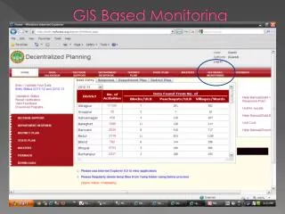
Explore how RDII impacts sewer systems, and learn about flow monitoring technology and optimal meter placement to minimize I/I issues. Discover various methods and models used to improve sewer flow monitoring efficiency.

E N D
Chris Skehan Improving Sewer Flow Monitoring using Spatial Optimization in GIS
Today’s Outline • What is RDII // Studying RDII • The Monitor • Discussion of the Problem • Design and Methods • Results
Rain Derived Inflow and Infiltration • Also known as RDII, I/I, or I&I • RDII is the main cause of SSO’s, street and basement flooding, and can damage to nearby receiving waters • Capacity Issues • Aging infrastructure, point source, indirect • National and local interest to measure, reduce, and eliminate RDII
Flow Monitoring Technology Flow monitoring technology is able to log sewer flow data in a given collection system over a unit time. These measurements can then be compared to each other meter, to a storm event, to a land area, etc.
Flow Monitor Placement • Mitchell and Stevens (2005) provide a guideline for determining the number of Flow Monitors • Limit your upstream influence to 10,000 - 15,000 LF at locations convergence point (8,500) • Limits greater than 15,000 LF will often dilute results • So where do we put these meters now that we have a range???
Well…. • …Flow Monitoring: sewage flow rates are monitored at various locations within the municipal sewage collection system. The flow data is analyzed, along with rainfall data, to determine if there is excessive I&I within the study area. • …by inserting special measuring devices into the sewer lines, crews can monitor the water flowing through them. If the flow increases during rainstorms, it's a sure sign of infiltration. • …Flow meters are being installed in five strategic locations around the city providing a true measurement of the amount of wastewater being carried by the City collection system. The information gathered from these devices will help to identify, monitor and manage the City’s I & I issues. • Meet all objective of study • Gathers all necessary data needed to reduce and eliminate majority of I/I • Minimizes Cost – Maximizes Value • Respect Target Areas (Worst First!)
The Problem Continued • Currently there is no standard methodology for determining the optimal placement of a flow monitor • As the size of the system increases, determining optimal placement becomes difficult • Range of limits can cause problems • Example – 3,000,000 LF – 200 to 300 flow monitors • Very Little Flexible & Time Consuming
The Problem Continued • Conundrum exists between the number of monitors and their placement in the system ~9,000 LF ~19,000 LF ~10,000 LF** **However – 1 additional meter was consumed
Non-Optimized Methods • Ad-Hoc – as large systems and studies will have many different results among engineers determining the flow monitors placement • Local Optimization Approach – Local, Zoomed, Fixed Extent to solve the location • Sequential Technique – Single monitor placement until all flow monitors are exhausted
Optimized Methods • Deterministic – Approach that will yield the same results every time, regardless of user • Global Optimization – Account for the entire system when determining results (problem areas can be weighted) • Simultaneous Technique – Solve for the placement of every meter used in the study simultaneously
Design • Utilize Operations Research (OR) – a proven methodology of optimization • Branches of OR - Graph Theory and Network Flows • The Facility Location Problem (and Model) • P-Median Problem Locating P "facilities" relative to a set of "customers" such that the sum of the shortest demand weighted distance between "customers" and "facilities" is minimized. Professor Phil Kaminsky – University of California at Berkeley
10 5 5 14 2.7 2.3 1.0 4 2 3 2 2.2 0.9 0.8 2.1 1.0 2M 1 0.8 2.6 4.7 7
Imagine the problem for 3 million LF and 500,000 manholes One Way Network: where Math can help solve such a complex problem
Data And Methods • Used 3 GIS shapefile layers to complete this study • Lawrence sewer lines & manholes • Non-Optimized locations determined by Engineer in a 2009 study • Shapefiles were not topologically integrated, and had to be converted to standard geographical file format – Geometric Network • Topology is essential for creating a network layer and utilizing a facility location model
Data and Methods Continued • A Facility Location Model was used to solve this problem • 3 Keys to a Facility Location Problem • Defining the Network between facilities and clients • Calculating the Connections Costs • Calculating the Facility Costs
Data and Methods Continued • Network was defined by using the Directed Graph preserved in the Sewer Lines Layer • Connections Costs were calculated by building a distance matrix using length between each facility and client constraints was set (53 Facilities & 15,000 LF) • Facility Costs were assumed to be equal among all potential clients (all nodes equal)
Data and Methods Continued • Network Partitioning was utilized on both set of locations • Provided a way to compare the to location sets • Provided a good visual representation of any upstream influences to a flow monitor • May be a promising time saving feature for creating flow monitoring basins
Figure 4 – The Non-Optimized Locations hand selected by the engineer (Green Circles) vs. the Optimized Locations selected by the facility location model (Blue Squares).
Figure 5 – The Non-Optimized Locations and the calculated network partition for each location. Each color theme represents an individual basin that would influence the flow monitor located at the downstream point of convergence.
Figure 6 – The Optimized Locations and the calculated Network Partition for each location. Each color theme represents an individual basin that would influence the flow monitor located at the downstream point of convergence.
Table 1 - The statistical data which was extracted from the network partitioning for the non optimized locations versus the optimized locations. Note the increase in the Relative Efficiency and the percentage of system that would be monitored if the optimized locations would have been utilized during the study. In both examples, the average basin size is still within the limits of Stevens (2005) criteria.
Key Results • Non-optimized locations would monitor approximately 43% of the entire collection system versus 63% with the optimized locations • Relative Efficiency was 66% for the non-optimized locations vs. 100% for the optimized locations • Average Upstream Influence (basin size) increased from 10K vs. 14K (constraint can be adjusted as needed) • Still within the Limits of Stevens (2005) • Results were extracted in less than 60 minutes for the entire system (locations) • An estimated $100,000 in monitoring would have been needed to measure the additional sections of sewer system
Conclusion • A facility location model can be utilized to improve optimization for flow monitor placement in RDII studies • Flexible Approach in terms of constraints, time, and effort • Promising tool for time reduction in RDII studies
Considerations • Connection errors in data - termed “network islands” in this study • Accounting for lift stations – or any other directional flow connections of a collection system • Consider multiple results versus a single optimal result • Increase # of Meters to Use or use the as-many-as-needed function in the facility location model
Figure 8 – This figure shows the disconnected network areas represented in red, as the connected network is shown in black.