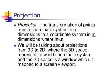

The Projection Matrix
E N D
Presentation Transcript
The Projection Matrix Lecture 29 Mon, Nov 5, 2007
Model Trans View Trans Proj Trans Object Coords World Coords Eye Coords Clip Coords M V P Lighting Calculations Clipping Perspective Divide Normal Dev Coords Window Coords Frame- buffer Rasterization, Shading Hidden-surface Removal, Texture Application The Graphics Pipeline
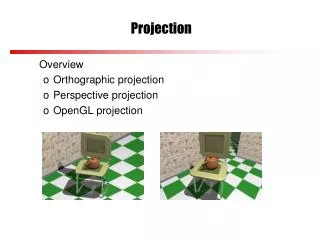
Homogeneous Coordinates • Points are stored in homogeneous coordinates (x, y, z, w). • The true 3D coordinates are (x/w, y/w, z/w). • Therefore, for example, the points (4, 3, 2, 1) and (8, 6, 4, 2) represent the same 3D point (4, 3, 2). • This fact will play a crucial role in the projection matrix.
Coordinate Systems • Eye coordinates • The camera is at the origin, looking in the negative z-direction. • View frustrum (right – left, bottom – top, near – far). • Normalized device coordinates • -1 x 1 • -1 y 1 • -1 z 1
The Transformation • Points in eye coordinates must be transformed into normalized device coordinates. • But first they are transformed to clipping coordinates.
The Transformation • For example, • The point (r, t, -n, 1) is first transformed to the point (n, n, -n, n). • The point (l(f/n), b(f/n), -f, 1) is first transformed to the point (-f, -f, f, f).
The Transformation • Later, OpenGL divides by the w-coordinate to get normalized device coordinates. • (n, n, -n, n) (1, 1, -1) • (-f, -f, f, f) (-1, -1, 1) • This is called the homogeneous divide, or perspective division. • It is a nonlinear transformation. • It occurs at a later stage in the pipeline.
The Perspective Transformation – x, y • Points in eye coordinates are projected onto the near plane, sort of. • The x- and y-coordinates are projected onto the near plane. • The z-coordinated is scaled to the range [-n, f].
near plane P(x, y, z) t -n -f b The Perspective Transformation – x, y • Consider the projection in the yz-plane.
The Perspective Transformation – x, y • Consider the projection in the yz-plane. near plane P(x, y, z) t y -f -z b
near plane P(x, y, z) t y -f n b The Perspective Transformation – x, y • Consider the projection in the yz-plane. y -z
The Perspective Transformation – x, y • By similar triangles, y/n = y/(-z), • Therefore, • Similarly,
The Perspective Transformation – x, y • Notice that these transformation are not linear. • That is, x and y are not linear combinations of x, y, and z. • Therefore, this transformation cannot be carried out by matrix multiplication. • We will perform the multiplication by n using a matrix, but dividing by -z, i.e., w, will have to be postponed.
The Perspective Transformation – z • The z-coordinate is handled differently because we must not lose the depth information yet. • In the z-direction, we want to map the interval [-n, -f] to the interval [-n, f]. • Later, the perspective division will map [-n, f] into [-1, 1].
The Perspective Transformation – z • Since this is a linear transformation, we will have z = az + b, for some a and b, to be determined. • We need • Therefore,
The Perspective Transformation • That is, we will map (r, t, -n, 1) (nr, nt, -n, n), (l(f/n), b(f/n), -f, 1) (fl, fb, f, f), etc. which is a linear transformation. • These points are equivalent to (r, t, -1), (l, b, 1), etc.
The Perspective Transformation • The perspective matrix is Represents division by –z (perspective division)
The Perspective Transformation • This transforms this frustum… P(x, y, z) t -n -f b
The Perspective Transformation • …into this frustum ft P(x, y, z) nt -n f nb fb
The Perspective Transformation • Later, the perspective division will transform this into a cube. 1 P(x, y, z) 1 -1 -1
The Perspective Transformation • Verify that P1 maps • (r, t, -n, 1) (nr, nt, -n, n) (r, t, -1) • (l, t, -n, 1) (nl, nt, -n, n) (l, t, -1) • (r, b, -n, 1) (nr, nb, -n, n) (r, b, -1) • (l, b, -n, 1) (nl, nb, -n, n) (l, b, -1) • (r(f/n), t(f/n), -f, 1) (fr, ft, -f, f) (r, t, -1) • (l(f/n), t(f/n), -f, 1) (fl, ft, -f, f) (l, t, -1) • (r(f/n), b(f/n), -f, 1) (fr, fb, -f, f) (r, b, -1) • (l(f/n), b(f/n), -f, 1) (fl, fb, -f, f) (l, b, -1)
The Projection Transformation • The second part of the projection maps • (nr, nt, -n, n) (n, n, -n, n) (1, 1, -1) • (nl, nt, -n, n) (-n, n, -n, n) (-1, 1, -1) • (nr, nb, -n, n) (n, -n, -n, n) (1, -1, -1) • (nl, nb, -n, n) (-n, -n, -n, n) (-1, -1, -1) • (fr, ft, -f, f) (f, f, f, f) (1, 1, 1) • (fl, ft, -f, f) (-f, f, f, f) (-1, 1, 1) • (fr, fb, -f, f) (f, -f, f, f) (1, -1, 1) • (fl, fb, -f, f) (-f, -f, f, f) (-1, -1, 1)
The Projection Transformation • The matrix of this transformation is
The Projection Matrix • The product of the two transformations is the projection matrix.
The Projection Matrix • The function glFrustum(l, r, b, t, n, f) creates this matrix and multiplies the projection matrix by it. glMatrixMode(GL_PROJECTION); glLoadIdentity(); glFrustum(l, r, b, t, n, f);
The Projection Matrix • The function gluPerspective(angle, ratio, near, far) also creates the projection matrix by calculating r, l, t, and b. glMatrixMode(GL_PROJECTION); glLoadIdentity(); gluPerspective(angle, ratio, n, f);
The Projection Matrix • The formulas are • t = n tan(angle/2) • b = -t • r = t ratio • l = -r
Question • When choosing the near and far planes in the gluPerspective() call, why not let n be very small, say 0.000001, and let f be very large, say 1000000.0?
Orthogonal Projections • The matrix for an orthogonal projection is much simpler. • All it does is rescale the x-, y-, and z-coordinates to [-1, 1]. • The positive direction of z is reversed. • It represents a linear transformation; the w-coordinate remains 1.
Orthogonal Projections • The matrix of an orthogonal projection is