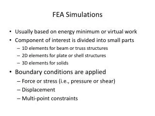
Finite Element Analysis of Carbon Fiber and TPG Composite Structures Under Thermal Loads
50 likes | 193 Vues
This study presents a detailed finite element analysis (FEA) of composite materials, including carbon fiber and TPG, considering their isotropic and anisotropic properties. Key parameters such as Young’s modulus, Poisson’s ratio, and thermal conductivity are analyzed. Results demonstrate temperature variations under a heat load of 2.28W, examining the thermal behavior and stress distribution across layers. The analysis identifies maximum resultant displacements and stresses within the structure, providing insights into the performance of these materials in thermal management applications.

Finite Element Analysis of Carbon Fiber and TPG Composite Structures Under Thermal Loads
E N D
Presentation Transcript
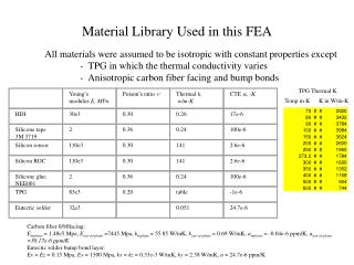
Young’s modulus E, MPa Poison’s ratio n Thermal k, w/m-K CTE a, /K HDI 30e3 0.30 0.26 17e-6 Silicone tape 3M 3719 2 0.36 0.24 100e-6 Silicon sensor 110e3 0.30 141 2.6e-6 Silicon ROC 110e3 0.30 141 2.6e-6 Silicone glue NEE001 2 0.36 0.24 100e-6 TPG 83e3 0.20 table -1e-6 Eutectic solder 32e3 0.051 24.7e-6 Material Library Used in this FEA All materials were assumed to be isotropic with constant properties except - TPG in which the thermal conductivity varies - Anisotropic carbon fiber facing and bump bonds TPG Thermal K Temp in K K in W/m-K Carbon fiber 0/90facing: Einplane = 1.48e5 Mpa, Eout-of-plane =7445 Mpa, kinplane= 55.85 W/mK, kout-of-plane = 0.69 W/mK, ainplane = -0.04e-6 ppm/K, aout-of-plane=30.17e-6 ppm/K Eutectic solder bump bond layer: Ex = Ez = 0.15 Mpa, Ey = 1500 Mpa, kx = kz = 0.33e-3 W/mK, ky = 2.38 W/mK, a = 24.7e-6 ppm/K
RESULTS WITH CF/TPG/CF SUBSTRATE 0.6 mm (0.12+0.38+0.12) mm COOLING AT ENDS Overall ∆T = 22C From +7C to +29C Heat Load = 2.28W , Half Model with 4 chips ∆T, substrate = 12.8C From +7C to 19.8C ∆T, HDI = 14.6C From +12.2C to +26.8C ∆T, sensor/ROC = 2.9C From +26.1C to +29C
RESULTS WITH CF/TPG/CF SUBSTRATE 0.6 mm (0.12+0.38+0.12) mm COOLING AT ENDS Heat Load = 2.28W , Half Model with 4 chips Max resultant displacement = 2 microns
RESULTS WITH CF/TPG/CF SUBSTRATE 0.6 mm (0.12+0.38+0.12) mm COOLING AT ENDS Heat Load = 2.28W , Half Model with 4 chips TPG Layer Max Resultant Stress = 1.25 Mpa Max Stress_Z = 0.13 Mpa Flexural Strenth = 36.7 Mpa Z = 38.5 Mpa // Tensile Strength < 0.69 Mpa Z = 6,897 Mpa // Stress Z Plot (out-of-plane direction)
RESULTS WITH CF/TPG/CF SUBSTRATE 0.6 mm (0.12+0.38+0.12) mm COOLING AT ENDS Heat Load = 2.28W , Half Model with 4 chips Stress Resultant Plot Stress Z Plot (out-of-plane 900direction) Carbon Fiber Layer Max Resultant Stress_X = 0.1 Mpa Max Stress_Z = 0.9 Mpa Flexural Strenth = 669 Mpa 00 Tensile Strength =1950 Mpa 00 = 28 Mpa 900