Download
1 / 4
40 likes | 72 Vues
The induction motor equivalent circuit parameters are required for many performance and planning studies involving induction motors. These parameters are typically calculated from standardized motor performance tests, such as the no load, full load, and locked rotor tests. However, standardized test data is not typically available to the end user. Alternatively, the equivalent circuit parameters may be estimated based on published performance data for the motor. Methodologies for obtaining the parameters of the equivalent circuit for an induction motor from the information on the nameplate and an analysis is presented so that the typical parameters of an equivalent circuit can be readily estimated. Anushree Rajendrarao Helonde | Mr. Mahesh Mankar "Identifying Three Phase Induction Motor Equivalent Circuit Parameters from Nameplate Data by Different Analytical Methods" Published in International Journal of Trend in Scientific Research and Development (ijtsrd), ISSN: 2456-6470, Volume-3 | Issue-3 , April 2019, URL: https://www.ijtsrd.com/papers/ijtsrd22934.pdf Paper URL: https://www.ijtsrd.com/engineering/electrical-engineering/22934/identifying-three-phase-induction-motor-equivalent-circuit-parameters-from-nameplate-data-by-different-analytical-methods/anushree-rajendrarao-helonde<br>

E N D
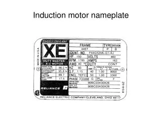
International Journal of Trend in Scientific Research and Development (IJTSRD) Volume: 3 | Issue: 3 | Mar-Apr 2019 Available Online: www.ijtsrd.com e-ISSN: 2456 - 6470 Identifying Three Phase Induction Motor Equivalent Circuit Parameters from Nameplate Data by Different Analytical Methods Anushree Rajendrarao Helonde1, Mr. Mahesh Mankar2 1M.Tech Student, 2Company Employee 1Shri Ramdeobaba College of Engineering and Management, Nagpur, Maharashtra, India 2Paramount Conductors Limited, Nagpur, Maharashtra, India How to cite this paper: Anushree Rajendrarao Helonde | Mr. Mahesh Mankar "Identifying Three Phase Induction Motor Equivalent Circuit Parameters from Nameplate Data by Different Analytical Methods" Published in International Journal of Trend in Scientific Research and Development (ijtsrd), ISSN: 2456- 6470, Volume-3 | Issue-3, April 2019, pp.642-645, URL: http://www.ijtsrd.co m/papers/ijtsrd229 34.pdf Copyright © 2019 by author(s) and International Journal of Trend in Scientific Research and Development Journal. This is an Open Access article distributed under the terms of the Creative Commons Attribution License (CC BY 4.0) (http://creativecommons.org/licenses/ by/4.0) I. INTRODUCTION The induction motor equivalent circuit parameters are usually computed from DC, no load, and blocked rotor test data as per IEEE Standard 112. For most commercially available or previously installed motors, however, neither the original test data nor the equivalent circuit parameters are available from the motor manufacturer. In many cases, only the motor nameplate data are available. These data include the rated voltage, rated output power, speed, efficiency, and power factor of the motor, its NEMA (National Electrical Manufacturers Association) design characteristics. However, the performance of induction motor (IM) might change whenever there are fluctuations in load and it could cause damage to the motor or other components if the motor works exceed the rated values. Thus, the equivalent circuit of an induction motor is a very useful tool in order to determine the motor response to the changes in load. The study is proposed to develop a simulation model to identify the parameter of induction motor using MATLAB/Simulink. In this paper, the conventional technique of three basic tests that are dc test, no-load test, and blocked ABSTRACT The induction motor equivalent circuit parameters are required for many performance and planning studies involving induction motors. These parameters are typically calculated from standardized motor performance tests, such as the no load, full load, and locked rotor tests. However, standardized test data is not typically available to the end user. Alternatively, the equivalent circuit parameters may be estimated based on published performance data for the motor. Methodologies for obtaining the parameters of the equivalent circuit for an induction motor from the information on the nameplate and an analysis is presented so that the typical parameters of an equivalent circuit can be readily estimated. KEYWORDS: MATLAB, ETAP, three phase IM equivalent circuit, DC test, No-Load Test, Blocked Rotor Test IJTSRD22934 rotor test are used and calculations are done based upon the results obtained from the simulation study. The dc, no-load and blocked rotor tests simulation models are developed by using MATLAB/Simulink. Another novel technique is also proposed to estimate performance characteristics from motor parameters and manufacturer’s data. This technique uses estimating the performance characteristics like current, speed, power factor, efficiency and torque from the mathematical formulae relating with the equivalent circuit parameters. This method describes ETAP simulation of three phase IM to identify equivalent circuit parameters. The computed values of the performance parameters have been compared with actual values for verification and validation of the technique. In this paper, the results obtained from both the methodologies are compared with respect to their individual parameters and percentage error has been computed to determine the success rate of the methods applied in both @ IJTSRD | Unique Paper ID – IJTSRD22934 | Volume – 3 | Issue – 3 | Mar-Apr 2019 Page: 642
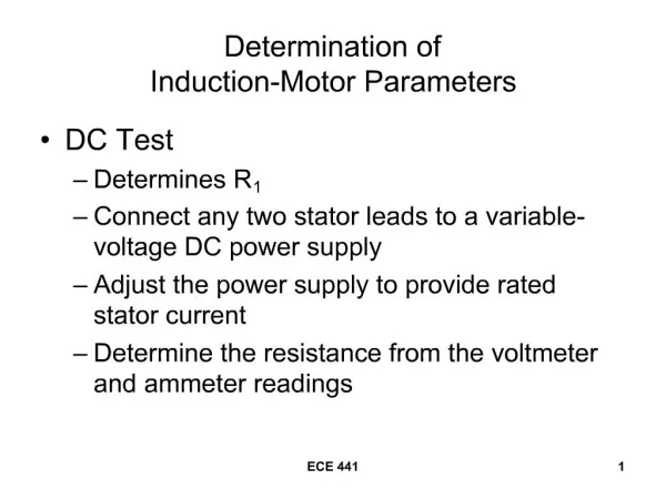
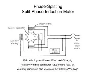
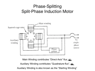
International Journal of Trend in Scientific Research and Development (IJTSRD) @ www.ijtsrd.com eISSN: 2456-6470 the cases. In order to implement a comparison, same motor has been used on both the methods. A.Three phase Induction Motor Equivalent Circuit The steady-state operating characteristics of a three-phase IM are often investigated using a per-phase equivalent circuit as shown in Figure 1. A voltage source is applied to the phase A and B of the induction motor through a series RC branch, while the phase C is grounded. The diagram has an induction motor block; this block contains the parameters that are needed to determine the induction motor tests. In this test, the DC voltage and DC current were recorded and Rs value is calculated. B.No-Load Test The no-load test on an induction motor is conducted to measure the rotational losses of the motor and to determine some of its equivalent circuit parameters (Rc, Xm). In this test, the stator terminals are supplied by balanced voltages at the rated frequency with the rotor uncoupled from any mechanical load. At the motor input, the current, voltage and power are measured. Total losses of core losses, winding losses, windage and friction are said as the losses in the no- load test. Figure1. Per Phase Equivalent Circuit referred to stator. In this circuit, Rs and Xs represent stator resistance and leakage reactance, respectively; Rr and Xr denote the rotor resistance and leakage reactance referred to the stator, respectively; Rc resistance stands for core losses; Xm represents magnetizing reactance; and s denotes the slip. The equivalent circuit is used to facilitate the computation of various operating quantities, such as stator current, input power, losses, induced torque, and efficiency. When power aspects of the operation need to be emphasized, the shunt resistance Rc is usually neglected; the core losses can be included in efficiency calculations along with the friction, windage, and stray losses. In the following method 1, MATLAB simulation setup for each tests are described on the following motor parameters: Power-4kW, Voltage-380V, Current-8.6A, Speed-1423rpm, No of Poles-4, Power Factor-0.85, Efficiency-83% Rated Torque (Tr)- 26.8 Nm, Maximum Torque (Tmax)-75.04 Nm. II. MATLAB/SIMULINK METHOD The various tests from the MATLAB/Simulink simulation test models will be used to calculate different parameters of the equivalent diagram. A.DC Test The DC Test is performed to compute the stator winding resistance Rs. A dc voltage is applied to the stator windings of an induction motor. The resulting current flowing through the stator windings is a dc current; thus there is no voltage induced in the rotor circuit, and the motor reactance is zero. The stator resistance is the only circuit parameter limiting current flow and can be computed. Simulation diagram for the DC test stator resistance is depicted in Figure 2. Figure3. Simulation Diagram of No-Load Test In the simulation test, a rated balanced AC voltage of 220Vrms per-phases with a rated frequency of 50Hz was applied to the stator and rotor runs without any load. The Simulink diagram of the no-load test is given in Figure 3. We also used the same induction motor for the DC test. The Y- connected 3-phase ideal voltage (phase A, phase B and phase source is connected to the stator windings. A zero mechanical load was applied to the rotor of the induction motor (input terminal Tm) to simulate the no-load condition. Some measurement blocks have been added to the diagram to measure some of the electrical and mechanical quantities, which are the Real and reactive power for the phase A (phase-A-power), the rms currents of the phases (abc-rms- currents), mechanical speed (mech-speed, ωm), electrical torque (elect-torque, Te) etc. C.Blocked Rotor Test The blocked-rotor test on an induction motor is performed to determine some of its equivalent circuit parameters (Rr, Xs+ Xr). In this test, in order to prevent rotation, the rotor is blocked. The balanced voltages are then applied to the stator terminals by using frequency which is 25 percent of the rated frequency and at a voltage where the rated current is achieved. Voltage, current, and power are measured at the motor input. Figure2. Simulation Diagram of DC Test Figure4. Simulation diagram of Blocked-Rotor Test @ IJTSRD | Unique Paper ID - IJTSRD22934 | Volume – 3 | Issue – 3 | Mar-Apr 2019 Page: 643
International Journal of Trend in Scientific Research and Development (IJTSRD) @ www.ijtsrd.com eISSN: 2456-6470 We used the same induction motor parameters as the no- load test. However, in order to simulate blocked rotor condition, we set the inertia of the rotor to infinite. In this test, the rotor is locked. A three-phase AC voltage was applied to the motor and adjusted to an appropriate value so that the current flow of each phase is equal to its rated value. Recall that the rated current is 8.6A, the simulation was run at various frequencies and data obtained on phase A current (IA), phase A RMS voltage (VA) and phase A input real and reactive powers (PA, QA). III. CALCULATIONS The various tests for the machine are carried out in the MATLAB/SIMULINK simulation software and the data obtained are employed in the calculations below. A.DC Test R1= Vdc = 94.02 = 3.92Ω 2×Idc 2×11.98 B.Block-Rotor Test The values obtained from the blocked rotor test simulation at various frequencies are given in the table below and different formulae are used to calculate the parameters (Rr, Xs and Xr). TABLE 1 BLOCKED ROTOR TEST Va rms (V) 108 8.56 632.39 663.57 128 8.65 530.69 973.39 145 8.47 341.12 974.45 Test Ia (A) Pa (W) Qa (Var) Wm Frequenc (Hz) 40 50 60 (rad/sec) 0 0 0 At each frequency RLR and XLR are computed using the following formulas: ZLR = VA/IA; PF = cosΦ= PA/VA x IA, ZLR = RLR + j X’LR = ZLR cosΦ + jZLR sinΦ. After calculating values at each frequency, average of all the values are taken to calculate Rr, Xs & Xr from RLRavg and X’LRavg respectively. At 40Hz, ZLR1 = 12.61Ω; cosΦ = 0.68; sinΦ = 0.72; RLR1 = 8.57Ω; X’LR1 = 9.07Ω. At 50Hz, ZLR2 = 14.79Ω; cosΦ = 0.47; sinΦ = 0.87; RLR2 = 6.95Ω; X’LR2 = 12.86Ω At 60Hz, ZLR3 = 17.11Ω; cosΦ = 0.27; sinΦ = 0.96; RLR3 = 4.61Ω; X’LR3 = 16.42Ω So, RLRavg= 6.71Ω; Rr = RLRavg–Rs = 2.786Ω. So, X’LRavg= 12.78Ω; Xs = Xr = 0.5X’LR avg = 6.39Ω. C.No-Load Test The values obtained from the no load test simulation at rated frequency and rated voltage are given in the table below and different formulae are used to calculate the parameters (Xm). TABLE 2NO LOAD TEST Ic Va Vb Vc Ia Ib Pa Qa Te ωm 220V 220V 220V 1.54A 1.54A 1.54A 57.53W 336.10VAr 0.91Nm 156.47rad/sec Xm+Xs ≈ Va/Ia≈ 142.85Ω. OR Xm+Xs = Qa/(Ia²) = 141.71Ω. So, Xm = 135.32Ω. D.Error TABLE 3PERCENTAGE ERROR PER PARAMETER Actual Values Rs 3.9Ω Xs 6.6Ω Xm 136.5Ω Xr 6.6Ω Rr 4.2Ω IV. ELECTROMAGNETIC PROGRAM (ETAP) METHOD Name plate data of motor given as input to ETAP. STEP 1: Click on the “Nameplate” tab and populate the “Ratings” frame with the following data: HP or kW, kV, %PF@100%, %Eff@100%, %Slip, Poles. STEP 2: Click on the “Imp” tab and observe the following data: %Locked Rotor Current, Locked Rotor Current. Locked Rotor kVA/HP, %PF, Tmax, Trated, Tlr. Note: Trated ≈ Tlr. STEP 3: Click on the “Model” tab and click on parameter estimation and tuning. STEP 4: On the “Solution Parameters” frame, enter the “Precision” and “Acceleration Factor”. The default values are 10% and 0.25 respectively. New values are supposed to be 2% and 0.25 respectively. Under the “Report Selection List”, select “Prompt”. This selection will prompt you for report file name when you perform the estimation (by clicking the “Estimate” button). Click the “Estimate” button. STEP5: After estimating parameters from “ETAP parameter estimator”, those values are put in an equation consisting of base impedance of the motor by the following method: V1=Vline/√3; Zbase= V1/Irated. The Zbase is then multiplied to the percentage value of the parameters obtained from the software to get the final answer. Note: In some cases, you might encounter “Error” message when you perform the estimation. This means that ETAP cannot estimate the motor circuit parameters based on the Input Data and Solution parameters. Input data should be re-evaluated and necessary adjustments should be made accordingly. V. CALCULATIONS A.Base calculations V1 = 380V Zbase = V1/I = 380/8.6 = 44.18Ω Rs = (8.027/100) x44.18 = 3.5463Ω Xs = (11.47/100) x44.18 = 5.0674Ω Xm = (223.814/100) x44.18 = 98.8810Ω Rc = (5573.938/100) x44.18 = 2462.5658Ω Rr,lr = (2.197/100) x44.18 = 0.9706Ω Rr, fl = (4.999/100) x44.18 = 2.2085Ω Xr, lr = (2.101/100) x44.18 = 0.9282Ω Xr, fl = (10.058/100) x44.18 = 4.4436Ω Calculated Values 3.92Ω 6.39Ω 135.32Ω 6.39Ω 2.786Ω % Parameter Error -0.005 3.18 0.86 3.18 33.66 TRANSIENT ANALYSIS @ IJTSRD | Unique Paper ID - IJTSRD22934 | Volume – 3 | Issue – 3 | Mar-Apr 2019 Page: 644
International Journal of Trend in Scientific Research and Development (IJTSRD) @ www.ijtsrd.com eISSN: 2456-6470 [5]An Off-Line Technique for Prediction of Performance Characteristics of Three Phase Induction Motor” Dr C V Ghule, Mrs Suhasini S D, Mrs Jewel Samanta, International Journal of Engineering Research & Technology (IJERT) Vol. 2 Issue 1, January- 2013 ISSN: 2278-0181 B.Error TABLE 4PERCENTAGE ERROR PER PARAMETER Actual Values Rs 3.9Ω Xs 6.6Ω Xm 136.5Ω Xr 6.6Ω Rr 4.2Ω Rc 1382.0 VI. CONCLUSION Two methods to determine equivalent parameters of IM were studied and implemented. The first method from the paper was employed in MATLAB environment and model simulations were carried out. In this method, core resistance is neglected and hence its value is not computed. Parameters obtained from these simulation tests help in determining the values of Rs, Rr, Xs, Xr, Xm for the IM as well as verify the practical test values for further verification. The second method was implemented in ETAP environment and the values were evaluated and compared to the actual values. In this method, the software programmed plays an important role in the solution to obtain the answers. Also, core resistance can be calculated. From the two methods, the first method has produced less error as compared to the other method by a large margin. Therefore, it is a better tool to verify not only the test results but also find the actual values of the parameters of IM. REFERENCES [1]IEEE Standard Test Procedure for Polyphase Induction Motors and Generators, IEEE Std. 112, 2004. Calculated Values 3.5463Ω 5.0674Ω 98.8810Ω 4.4436Ω 2.2085Ω 2462.5658Ω % Parameter Error 9.06 23.22 27.55 32.72 47.41 -78.18 [6]Haque, M. H. "Estimation of three-phase induction motor parameters." Electric power systems research 26.3 (1993): 187-193. [7]Abdelaziz, Morad, and Ehab F. El-Saadany. "Estimation of induction motor single-cage model parameters from manufacturer data." Power and Energy Society General Meeting (PES), 2013 IEEE. IEEE, 2013. [8]Rahmatul Hidayah Salimin, Siti Hajar Binti Abd Kadir, Shah Rizam Mohd. Shah Baki, Faridah Ismail “Parameter Identification of Three-Phase Induction Motor using MATLAB-Simulink” IEEE 7th International Power Engineering and Optimization Conference. Langkawi. Malaysia. June 2013. [9]“A review on electrical motors energy use and energy savings”, R. Saidur Department of Mechanical Engineering, University of Malaya, Kuala Lumpur, Malaysia, 2009 Elsevier Ltd. All rights reserved. [10]“Research on Identification of Induction Motor Parameters Based on Nameplate Data” Xingwu Wang, Zhaoyan Zhang, and Yongjun Lin Applied Mechanics and Materials Vol 721 (2015) pp 517-522 Submitted: 2014-10-28 © (2015) Trans Tech Publications, Switzerland. [11]“Parameter Determination of Asynchronous Machines From Manufacturer Data Sheet” Joao Marcondes Correa Guimaraes, Jose Vitor Bernardes, Jr., Antonio Eduardo Hermeto, and Edson da Costa Bortoni IEEE Transactions On Energy Conversion, Vol. 29, No. 3, September 2014. [2]M. Haque, "Determination of NEMA design induction motor parameters from manufacturer data," IEEE Transactions on Energy Conversion, vol. 23, no. 4, pp. 997-1004, Dec. 2008. [3]Lee, Keun, et al. "Estimation of induction motor equivalent circuit parameters from nameplate data." North American Power Symposium (NAPS), 2012. IEEE, 2012. [12]“A Comparative Analysis of Three Phase Induction Motor Performance Evaluation” France O. Akpojedje, Ese M. Okah, and Yussuf O. Abu International Journal of Engineering and Techniques - Volume 2 Issue 3, May – June 2016. [4]Pedra, J., and L. Sainz. "Parameter estimation of squirrel-cage induction motors without torque measurements." IEE Proceedings-Electric Power Applications 153.2 (2006): 263-270. @ IJTSRD | Unique Paper ID - IJTSRD22934 | Volume – 3 | Issue – 3 | Mar-Apr 2019 Page: 645