Download
1 / 4
40 likes | 58 Vues
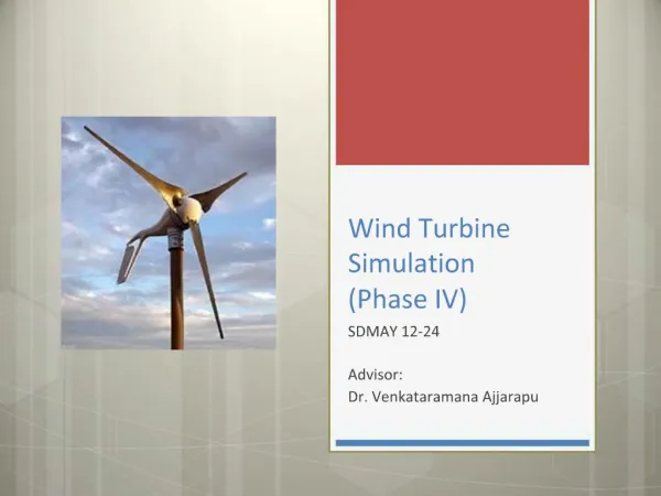
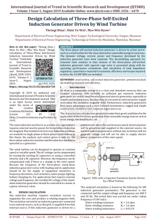
The three phase self excited induction generator is driven by prime mover such as a wind turbine for the clean alternative renewable energy in rural area. The dynamic voltage, current, power and frequency developed by the induction generator have been analyzed. The dq modeling approach for transient state analysis in time domain of the three phase self excited induction generator with squirrel cage rotor is presented along with its operating performance evaluations. And calculation of total impedance regulation, capacitance required to excitation, efficiency and torque required to drive the 3.6 kW SEIG are included. Theingi Htun | Hnin Yu Wai | Myo Win Kyaw "Design Calculation of Three-Phase Self-Excited Induction Generator Driven by Wind Turbine" Published in International Journal of Trend in Scientific Research and Development (ijtsrd), ISSN: 2456-6470, Volume-3 | Issue-5 , August 2019, URL: https://www.ijtsrd.com/papers/ijtsrd26728.pdf Paper URL: https://www.ijtsrd.com/engineering/electrical-engineering/26728/design-calculation-of-three-phase-self-excited-induction-generator-driven-by-wind-turbine/theingi-htun<br>

E N D
International Journal of Trend in Scientific Research and Development (IJTSRD) Volume 3 Issue 5, August 2019 Available Online: www.ijtsrd.com e-ISSN: 2456 – 6470 Design Calculation of Three-Phase Self-Excited Induction Generator Driven by Wind Turbine Theingi Htun1, Hnin Yu Wai1, Myo Win Kyaw2 1Department of Electrical Power Engineering, West Yangon Technological University, Yangon, Myanmar 2Department of Electrical Power Engineering, Technological University Mandalay, Mandalay, Myanmar How to cite this paper: Theingi Htun | Hnin Yu Wai | Myo Win Kyaw "Design Calculation of Three-Phase Self-Excited Induction Generator Driven by Wind Turbine" Published in International Journal of Trend in Scientific Research and Development (ijtsrd), ISSN: 2456- 6470, Volume-3 | Issue-5, August 2019, https://doi.org/10.31142/ijtsrd26728 Copyright © 2019 by author(s) and International Journal of Trend in Scientific Research and Development Journal. This is an Open Access article distributed under the terms of the Creative Commons Attribution License (CC (http://creativecommons.org/licenses/by /4.0) The same induction machine is as a motor or is a generator it requires external reactive power for its excitation to develop the magnetic flux needed in its iron core. Induction machines are available in single-phase or three-phase constructions. In this thesis, the analysis and control given is only for the three-phase induction machine and the induction machine is operated as a generator. The wind turbine can be designed to operate at constant speed or variable speed. The AC voltage can be compensated by varying the exciting AC capacitors or using a controlled inverter and a DC capacitor. However, the frequency can be compensated only if there is a change in the rotor speed. Because the frequency of the three-phase stand-alone induction generator varies with loading and its application should be for the supply of equipment insensitive to frequency deviations, such as heaters, water pumps, lighting, battery charging etc. For applications that require constant voltage and frequency, the rectified DC voltage of the stand- alone induction generator should be controlled to remain at a given reference value. II. DESIGN CALCULATION Any induction machine requires excitation current to magnetize the core and produce a rotating magnetic field. The excitation current for an induction generator connected to an external source, such as the grid, is supplied from that external source. If this induction generator is driven by a ABSTRACT The three-phase self-excited induction generator is driven by prime mover such as a wind turbine for the clean alternative renewable energy in rural area. The dynamic voltage, current, power and frequency developed by the induction generator have been analyzed. The dq-modeling approach for transient state analysis in time domain of the three-phase self-excited induction generator with squirrel cage rotor is presented along with its operating performance evaluations. And calculation of total impedance regulation, capacitance required to excitation, efficiency and torque required to drive the 3.6 kW SEIG are included. KEYWORDS: wind turbine, self-excited induction generator, symmetrical fault, dq-modeling transient and efficiency. I. Introduction As wind is a renewable energy it is a clean and abundant resource that can produce electricity with virtually no pollutant gas emission. Induction generators are widely used for wind powered electric generation, especially in remote and isolated areas, because they do not need an external power supply to produce the excitation magnetic field. Furthermore, induction generators have more advantages such a cost, reduced maintenance, rugged and simple construction, brushless rotor (squirrel cage) and so on. The characteristics of induction generators make them good candidates for the application of electric power generation from renewable energy sources such as wind energy, low-head hydro, etc. prime mover above the synchronous speed, electrical power will be generated and supplied to the external source. An isolated induction generator without any excitation will not generate voltage and will not be able to supply electric power irrespective of the rotor speed. IJTSRD26728 pp.1431-1434, BY 4.0) Figure1. SEIG with a Capacitor Excitation System Driven by a Wind Turbine The analyzed calculation is based on the following 3.6 kW induction generator parameters. The generator is star connected and the output voltage and frequency are 400 V and 50 Hz. The tested data was carried out under radian frequency of 100 rad/s. Stator winding resistance Rotor winding resistance Stator winding inductance R1 = 1.6 ohm R2 = 1.6 ohm L1 = 0.012 H @ IJTSRD | Unique Paper ID – IJTSRD26728 | Volume – 3 | Issue – 5 | July - August 2019 Page 1431
International Journal of Trend in Scientific Research and Development (IJTSRD) @ www.ijtsrd.com eISSN: 2456-6470 Rotor winding inductance Nominal torque Number of pole Magnetizing inductance Rotor inertia L2 = 0.012 H = 50 Nm P = 6 Lm = 0.181 H J = 0.045 kgm2 50 120 Then, from Equation 4.10, 2 o I V R = 251.932 Ω m 2 o P R o 1 Taking load power such as; PL = [1000, 1200, 1400, 1600, 1800, 2000, 2200, 2400, 2600, 2800, 3000, 3200, 3400, 3600] W at 0.9 power 0.9 cos p.f cos θ For load power 1.8 kW at F = 0.7 p.u; From Equation 4.47, 2 ph LP L FP From Equation 4.46, R X F tan From Equation 4.45, 2 2 LP LP L 2 2 2 LP LP R F X 2 LP LP L 2 2 2 LP LP R F X L L L Z R FX = 114.2857 Ω And for unity power factor compensation, Xc = XL But, X X X X 1 2 2 F p X n 1000 So, the synchronous speed rpm s 6 factor lagging. So, For rotor speed is vary from 1000 rpm to 2000 rpm, the p.u slip is vary 0 to -1. For convenient analysis is obtained let the slip value in matrix form such as; s = [-0.00001,-0.008,-0.035,-0.055,-0.1,-0.12,-0.15,-0.18,-0.2,- 0.22,-0.24,-0.27,-0.3,-0.4,-0.5,-0.6,-0.7,-0.8,-0.9,-1] b a where, fL 2 X ; 20 fL 2 X So, X1 = 3.7699 Ω , X20 = 3.7699 Ω and Xm = 56.863 Ω. The rotor reactance is depend on the slip of generator, X2 = sX20. At s = -0.1, -0.37699 Ω; Where, s = 1.3497˚ 2 2 2 X s From Equation 4.4; 2 a m X Then, the magnitude of total impedance is; 1 1 25.842 V R = 42.328 Ω and a b Z R j X 1 1 2 2 2 2 a b LP 124.852 Ω LP X 2 fL ; 2 1 1 m m F X R R = 34.286; R X X = 23.722 Ω 2 2 R 2 2 Z And = 16.0044 Ω LP Xc = = 35.0372 Ω; LP 2 C = = 90.85 μF; cos θ sin θ 1 = 0.0625, = 0.0191 2 π f X c b Z Z 2 2 R R 2 1 X X 1 2 Fs = 128.118Ω; X X 2 2 1 2 2 a b = 18.215 Ω Z R X 1 1 2 2 2 2 R R a b a b 2 1 2 X X 1 2 = - 30.1872 Ω; The phase angle of the total impedance; 18.215 26.913 Z By using Equations 4.34 to 4.38, the following data are obtained for various slip under generator operation. Efficiency calculation of 3.6 kW SEIG; Core losses Rm can be determined by making the machine rotate experimentally at no load and measuring the active power per phase Po, the average voltage per phase Vo, and the average current per phase Io. So, the 3.6 kW SEIG is made to turn at the synchronous rotation (s = 0), to allow separation of the mechanical losses from the total losses. In practical, the data of P0, V0 and I0 are difficult to obtain. Therefore, assume nearly values of these variables as following to get convenient calculation. P0 = 275 W; V0 = 400 3 V; I0 = 6.29 A F Fs R p 26.913˚ R 2 R 1 Ω =16.233+j8.24 s 1 1 1 = 0.0349; R R R mL m LP RmL = 81.4787 Ω; Figure2. Equivalent Circuit of the Parallel Loaded Induction Generator @ IJTSRD | Unique Paper ID – IJTSRD26728 | Volume – 3 | Issue – 5 | July - August 2019 Page 1432
International Journal of Trend in Scientific Research and Development (IJTSRD) @ www.ijtsrd.com eISSN: 2456-6470 V ph I 2 1 s 3.2 3.393 j F 1.6 s = 23.2361A 2 ph V 1 s 2 2 2 2 I R I R R 2 1 2 s R m η 1 s 2 2 I R 2 s = 76.4954 % Torque calculation, The expression for electromagnetic torque for generator operation, in terms of the arbitrary reference variables is: From Equation 4.19, qr ds m e i i L 2 2 For 3.6 kW SEIG, Magnetizing inductance (Lm) Rotor inertia (J) ids = 11.7A; idr = -13.4A; iqs 3 0.181 11.7 2 2 = -110.54394 Nm And the torque and speed for the generator operation are related by the following expressions: P J D d 2 Where, ωs = 100 rad/s and TD = -1492.3432 Nm III. SIMULATION AND RESULTS The following curve is drawn by Matlab program application. In Figure 3, the total impedance is decreased after generator speed is greater than its synchronous speed. The total impedance is smallest between -0.4 and -0.8 p.u of the slip value. Figure4. Capacitance / Frequency of 3.6 kW SEIG 3 P T i i qs dr = 0.181H = 0.045 kgm2; = 0A; iqr = -11.6A 11.6 P Figure5. The Capacitance / Load Curve of 3.6 kW SEIG 0 So, Te = Figure 4 and Figure 5 are drawn by Matlab application., The capacitance required for the SEIG is increased as generator supplied load and F are increased. pω T T r e 2 4 0.045 ω (1 s) 110.54394 ; s ds Figure 6.The Efficiency / Slip Curve of 3.6 kW SEIG Figure7. The Efficiency / Rotor Reactance Curve of 3.6 kW SEIG The curves are drawn by Matlab program application in Figures 6 and 7 In Figure 6, the efficiency is negative when slip is in -0.00001 (i.e generator speed is in 1010 rpm). And the efficiency is higher when the slip is between -0.055 and - 0.1. So, the SEIG must be generated electrical power with the prime mover speed between 1020 and 1200 rpm. From Figure 7, the efficiency is higher when the rotor reactance is between -6.3 Ω and -8 Ω. Figure3. The Total Impedance / Slip Curve of 3.6 kW SEIG @ IJTSRD | Unique Paper ID – IJTSRD26728 | Volume – 3 | Issue – 5 | July - August 2019 Page 1433
International Journal of Trend in Scientific Research and Development (IJTSRD) @ www.ijtsrd.com eISSN: 2456-6470 IV. Power absorbed by a wind turbine is proportional to the cube of the wind speed. Wind turbines are designed to yield maximum output power at a given wind speed. In case of stronger wind, it is necessary to waste part of the excess energy of the wind in order to avoid damaging the wind turbine. At a particular speed the capacitance required for self- excitation, when the machine operates at no load, is less than the capacitance required for self-excitation when it is loaded. When an induction machine operates as a motor the speed of the rotating air gap magnetic field is totally dependent on the excitation frequency. However, in the SEIG, it is shown that the frequency of the generated voltage depends on the speed of the prime mover as well as the condition of the load. When the speed of the prime mover drops with load, then the decrease in voltage and frequency will be greater than for the case where the speed is held constant. Keeping the speed of the prime mover constant with increased load causes the magnitude of generated voltage and frequency of an isolated SEIG to decrease. . When the speed of the prime mover is varied the flux linkage in the induction generator is varied inversely proportional to the rotor speed so that the generated voltage will remain constant. Once a constant DC voltage is achieved a DC load can use it directly or, if required, it is a matter of having an inverter to produce a constant voltage and frequency AC output. Different types of vector control techniques are developed to control the excitation and the active power producing currents independently. That is, the current control scheme causes the currents to act in the same way as in a DC generator where the field current and the armature current are decoupled. DISCUSSIONANDCONCLUSION The analysis and explanations presented in this thesis provide a good foundation for further research in the area of isolated induction generators driven by a wind turbine. By studying this thesis, it can get not only the basic principle of induction generator theory but also the simulation model for SEIG. Therefore, this thesis will help to develop the technology in the renewable energy sources in Myanmar. REFERENCES [1]Godoy Simoes. M and Felix A. Farret,: Design and Analysis with Induction Generators, CRC Press, (2004). [2]Cathey, J. J.: Electric Machines: Analysis and Design Applying MATLAB, Mc Graw-Hill, New York, (2000). [3]Fukami. T, Y. Kaburaki, S. Kawahara, and T. Miyamoto,: Performance Analysis of Self-regulated and Self-excited Single-phase Inductance Machine using a Three-phase Machine, IEEE Trans, EC-(1999). [4]C. H, Lee, and L. Wang,: A Novel Analysis of Parallel Operated Self-excited Induction Generators, IEEE Trans, EC-(1998). [5]Bahrani,: Analysis of Self-excited Induction Generators Under Unbalanced Conditions, EMPS, vol.24, no.2, (1996). [6]Paul. C. Krause, Oleg Wasynczuk and Scott D. Sudhoff,: Analysis of Electric Machinery, IEEE Press, (1994). [7]Doxey, B. C,: Theory and application of the capacitor- excited induction generator, IEEE Press, (1992). [8]Grantham,: Steady-state and transient analysis of self- excited induction generators, IEEE, Proc, March (1989). @ IJTSRD | Unique Paper ID – IJTSRD26728 | Volume – 3 | Issue – 5 | July - August 2019 Page 1434