Datapath Design I
Datapath Design I. Systems I. Topics Sequential instruction execution cycle Instruction mapping to hardware Instruction decoding. Overview. How do we build a digital computer? Hardware building blocks: digital logic primitives Instruction set architecture: what HW must implement

Datapath Design I
E N D
Presentation Transcript
Datapath Design I Systems I • Topics • Sequential instruction execution cycle • Instruction mapping to hardware • Instruction decoding
Overview • How do we build a digital computer? • Hardware building blocks: digital logic primitives • Instruction set architecture: what HW must implement • Principled approach • Hardware designed to implement one instruction at a time • Plus connect to next instruction • Decompose each instruction into a series of steps • Expect that most steps will be common to many instructions • Extend design from there • Overlap execution of multiple instructions (pipelining) • Later in this course • Parallel execution of many instructions • In more advanced computer architecture course
Byte 0 1 2 3 4 5 nop 0 0 addl 6 0 halt 1 0 subl 6 1 rrmovl rA, rB 2 0 rA rB andl 6 2 irmovl V, rB 3 0 8 rB V xorl 6 3 rmmovl rA, D(rB) 4 0 rA rB D jmp 7 0 mrmovl D(rB), rA 5 0 rA rB D jle 7 1 OPl rA, rB 6 fn rA rB jl 7 2 jXX Dest 7 fn Dest je 7 3 call Dest 8 0 Dest jne 7 4 ret 9 0 jge 7 5 pushl rA A 0 rA 8 jg 7 6 popl rA B 0 rA 8 Y86 Instruction Set
valA Register file srcA A valW W dstW valB srcB B Clock fun A MUX 0 A L U = B 1 Clock Building Blocks • Combinational Logic • Compute Boolean functions of inputs • Continuously respond to input changes • Operate on data and implement control • Storage Elements • Store bits • Addressable memories • Non-addressable registers • Loaded only as clock rises
Hardware Control Language • Very simple hardware description language • Can only express limited aspects of hardware operation • Parts we want to explore and modify • Data Types • bool: Boolean • a, b, c, … • int: words • A, B, C, … • Does not specify word size---bytes, 32-bit words, … • Statements • bool a = bool-expr ; • int A = int-expr ;
HCL Operations • Classify by type of value returned • Boolean Expressions • Logic Operations • a && b, a || b, !a • Word Comparisons • A == B, A != B, A < B, A <= B, A >= B, A > B • Set Membership • A in { B, C, D } • Same as A == B || A == C || A == D • Word Expressions • Case expressions • [ a : A; b : B; c : C ] • Evaluate test expressions a, b, c, … in sequence • Return word expression A, B, C, … for first successful test
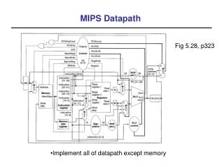
newPC SEQ Hardware Structure PC valE , valM Write back valM • State • Program counter register (PC) • Condition code register (CC) • Register File • Memories • Access same memory space • Data: for reading/writing program data • Instruction: for reading instructions • Instruction Flow • Read instruction at address specified by PC • Process through stages • Update program counter Data Data Memory memory memory Addr , Data valE CC CC ALU ALU Execute Bch aluA , aluB valA , valB srcA , srcB Decode A A B B dstA , dstB M M Register Register Register Register file file file file E E icode ifun valP rA , rB valC Instruction PC Instruction PC memory increment Fetch memory increment PC
newPC SEQ Stages PC valE , valM Write back valM • Fetch • Read instruction from instruction memory • Decode • Read program registers • Execute • Compute value or address • Memory • Read or write data • Write Back • Write program registers • PC • Update program counter Data Data Memory memory memory Addr , Data valE CC CC ALU ALU Execute Bch aluA , aluB valA , valB srcA , srcB Decode A A B B dstA , dstB M M Register Register Register Register file file file file E E icode ifun valP rA , rB valC Instruction PC Instruction PC memory increment Fetch memory increment PC
Optional Optional D icode 5 0 rA rB ifun rA rB valC Instruction Decoding • Instruction Format • Instruction byte icode:ifun • Optional register byte rA:rB • Optional constant word valC
Fetch Read 2 bytes Decode Read operand registers Execute Perform operation Set condition codes Memory Do nothing Write back Update register PC Update Increment PC by 2 Why? OPl rA, rB 6 fn rA rB Executing Arith./Logical Operation
Fetch icode:ifun M1[PC] Read instruction byte rA:rB M1[PC+1] Read register byte valP PC+2 Compute next PC Decode valA R[rA] Read operand A valB R[rB] Read operand B Execute valE valB OP valA Perform ALU operation Set CC Set condition code register Memory Write back R[rB] valE Write back result PC update PC valP Update PC Stage Computation: Arith/Log. Ops OPl rA, rB • Formulate instruction execution as sequence of simple steps • Use same general form for all instructions
Fetch Read 6 bytes Decode Read operand registers Execute Compute effective address Memory Write to memory Write back Do nothing PC Update Increment PC by 6 rA rB 4 0 rmmovl rA, D(rB) D Executing rmmovl
Fetch icode:ifun M1[PC] Read instruction byte rA:rB M1[PC+1] Read register byte valC M4[PC+2] Read displacement D valP PC+6 Compute next PC Decode valA R[rA] Read operand A valB R[rB] Read operand B Execute valE valB + valC Compute effective address Memory M4[valE] valA Write value to memory Write back PC update PC valP Update PC Stage Computation: rmmovl rmmovl rA, D(rB) • Use ALU for address computation
Fetch Read 2 bytes Decode Read stack pointer Execute Increment stack pointer by 4 Memory Read from old stack pointer Write back Update stack pointer Write result to register PC Update Increment PC by 2 popl rA b rA 0 8 Executing popl
Fetch icode:ifun M1[PC] Read instruction byte rA:rB M1[PC+1] Read register byte valP PC+2 Compute next PC Decode valA R[%esp] Read stack pointer valB R [%esp] Read stack pointer Execute valE valB + 4 Increment stack pointer Memory valM M4[valA] Read from stack Write back R[%esp] valE Update stack pointer R[rA] valM Write back result PC update PC valP Update PC Stage Computation: popl popl rA • Use ALU to increment stack pointer • Must update two registers • Popped value • New stack pointer
Summary • Today • Sequential instruction execution cycle • Instruction mapping to hardware • Instruction decoding • Next time • Control flow instructions • Hardware for sequential machine (SEQ)