PIC example test and PCB Design
Unit 4. Electronics Department. Microcontroler Lab. PIC example test and PCB Design. Mr. Banyat Somsupan. Electronic Ubontecnical. Introduction. PIC Microcontrollers are very advanced devices used in many embedded systems applications in our daily life applications.

PIC example test and PCB Design
E N D
Presentation Transcript
Unit 4 Electronics Department Microcontroler Lab PIC example test and PCB Design Mr. BanyatSomsupan Electronic Ubontecnical
Introduction PIC Microcontrollers are very advanced devices used in many embedded systems applications in our daily life applications Electronic Ubontecnical
เลือกเบอร์ Picที่จะพัฒนา PIC Microcontrollers มีทั้งขนาด40 ,28,18,8 ขา Electronic Ubontecnical
(1)เลือกเบอร์ PIC PIC12F675 มี 8 ขา ใช้ในพวก Remote Control ,Speed Control PIC16F628/PIC16F648A มี 18 ขา มMemory Programs 2K/4Kใช้ PIC16F648A ดีกว่า PIC18F458/877A มี40ขา MemoryPrograms 32K มีportใช้งานเยอะ เหมาะทำโครงงานเช่นเครื่องลงเวลาที่ใช้ทั้งLCD+Keyboard +EEPROM ภายนอก +RS232 หายห่วงเรื่องโปรแกรมขนาดโตๆๆ PIC18F258 มี Memory Programs 32K ตัวผอมๆ ใช้ในที่แคบๆที่ต้องการPort และMemoryมากๆ ใช้ทำเป็น Adapter ภายนอกดัดแปลงต่อกับ 40ขาได้ Electronic Ubontecnical
(2)เลือกเบอร์ PIC เทียบขาต่างๆของ PIC ที่ใช้ในการ Programs อ้างอิงจากhttp://www.thaimicrotron.com/PROPIC/MCU-PIN.html) Electronic Ubontecnical
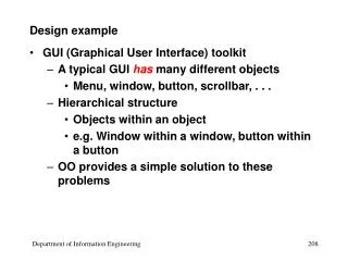
Outline • Hardware requirements for PIC • PIC diagram and implementation • PIC example on bread board • PCB Design Introduction • PCB design steps • Assignment (2) Electronic Ubontecnical
(1) Hardware REQ. for PIC 40 pins PIC Microcontrollers 16f877a Breadboard for testing / Cupper Plate for PCB Voltage regulator LM7805 4 MHz Crystal Oscillator 40 pins Connector for the PIC Microcontrollers Jumpers Batteries generating DC voltage Capacitors 22u Farrad Resistors 10k ohm LEDs with different colors for testing Electronic Ubontecnical
(1) Cont. Electronic Ubontecnical
Outline • Hardware requirements for PIC • PIC diagram and implementation • PIC example on bread board • PCB Design Introduction • PCB design steps • Assignment (2) Electronic Ubontecnical
(2) PIC Diagram PIC Microcontrollers Pins Layout Electronic Ubontecnical
(1) การโปรแกรมลงในตัว PIC. Key Code ด้วย MikroC Pro for Pic จะได้ ไฟล์ . C แล้ว Build เป็น . Hex นำ .HEX Electronic Ubontecnical
(2) การโปรแกรมลงในตัว PIC. ด้วยโปรแกรม Winpicc นำ .HEX Electronic Ubontecnical
(3) การโปรแกรมลงในตัว PIC. ด้วยโปรแกรม picKit 2 นำ .HEX Electronic Ubontecnical
(4) การโปรแกรมลงในตัว PIC. สังเกต จำนวนสายที่ใช้โปรแกรม มี 5 เส้น นำ .HEX นำ .HEX Electronic Ubontecnical
(5) การโปรแกรมลงในตัว PIC. Application Board Reset MCU Vpp/!MCLR Vdd Vss PGD PGC 10k 1 2 3 4 5 Vdd Vss Board +5V Supply Electronic Ubontecnical
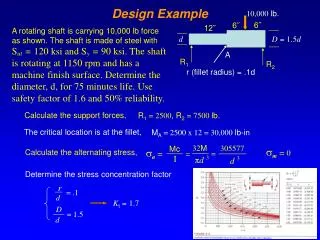
วงจรการการใช้ PIC The implemented schematic diagram Electronic Ubontecnical
(2) วงจรการใช้งาน Pic ไฟ +5 volt ต่อที่ขา VDD กราวด์ ต่อที่ขา VSS Electronic Ubontecnical
(3) วงจรการใช้งาน Pic 3. ต่อ Crystallที่ขา OSC1 และ OSC2 Electronic Ubontecnical
ค่าความถี่ที่เลือกใช้งานได้ค่าความถี่ที่เลือกใช้งานได้ Electronic Ubontecnical
(4) การต่อ Reset วงจร ต่อ Resister Pull Up ที่ขา MCLR ต่อสวิตซ์ Reset ที่ขา MCLR กับ กราวด์ Electronic Ubontecnical
Outline • Hardware requirements for PIC • PIC diagram and implementation • PIC example on bread board • PCB Design Introduction • PCB design steps • Assignment (2) Electronic Ubontecnical
วงจรการใช้งาน PIC16F628A Electronic Ubontecnical
(1) ภาคจ่ายไฟ + 5 Volt Electronic Ubontecnical
(2) Cont. The final Circuit implementation on bread board Electronic Ubontecnical
(3) PIC Example Write a C program to flash / blink LEDs to Rd0 voidmain(void) { TrisB=0; while(1) { PortB.F1=1; delay_ms(1000); PortB.F1=0; delay_ms(1000); } } // download the HEX file on the pic via the programmer and testing the blinking of LEDs Electronic Ubontecnical
Outline • Hardware requirements for PIC • PIC diagram and implementation • PIC example on bread board • PCB Design Introduction • PCB design steps • Assignment (2) Electronic Ubontecnical
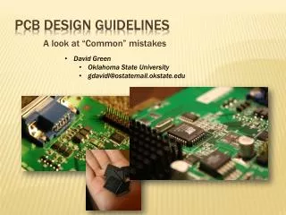
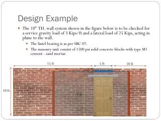
(4) PCB Design • PCBis used to mechanically support and electrically connect electronic components using conductive pathways, tracks or signal traces etched from copper sheets laminated onto a non-conductive substrate. It is also referred to as printed wiring board (PWB) or etched wiring board. • PCB Design is much better and having many advantages • 1) Clear design • 2) Make design away from short circuits • 3) Make inexpensive design • 4) Make Highly reliable design • 5) Faster design for high volume production Electronic Ubontecnical
(4) Cont. PCBis considered better than the design on bread board and more reliable without jumping wires and extensions that could be a reason for the short circuit (SC), so the bread board could be a way to test the hardware but could not be considered as final implementation Electronic Ubontecnical
Outline • Hardware requirements for PIC • PIC diagram and implementation • PIC example on bread board • PCB Design Introduction • PCB design steps • Assignment (2) Electronic Ubontecnical
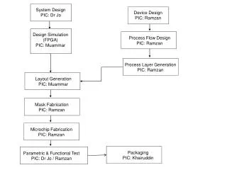
(5) PCB Design steps PCBhas many steps required for its design Make the schematic and design on EAGLE CADSOFT Print Design on two transparent papers with actual size of design Stick the two papers perfectly together Put it in the UV light machine and vacuum the air everywhere Electronic Ubontecnical
(5) Cont. 5) Take it directly to the developer solution and drop it many times inside it till all photoresist will be removed and the patterns of wires appear( from 1 - 2 mins) 6) Then put it inside the etching solution to get rid of all not needed copper and only remains the needed copper for wiring ( from 15 – 20 mins) and at 50 degrees Electronic Ubontecnical
(5) Cont. 7) Check under microscope if it contains short circuits (SC) or with Multimeter and if there is any short circuits etch it again till all is gone 8) Then put is again in UV light machine to get rid of all photoresist 9) Make holes required for the design by the drilling machine size 10) Start soldering ICs in its suitable places according to your design Electronic Ubontecnical
(5) Cont. These steps are required to design PCB and it should be done in reality .. But for simplicity hand out your design and you will get it printed and ready for soldering and integrating ICs on it. Soldering process will be discussed later in details Electronic Ubontecnical
Outline • Hardware requirements for PIC • PIC diagram and implementation • PIC example on bread board • PCB Design Introduction • PCB design steps • Assignment (2) Electronic Ubontecnical
Board ที่สร้างเสร็จแล้ว Electronic Ubontecnical
สวัสดี..ครับ บัญญัติ สมสุพรรณ แผนช่างอิเล็กทรอนิกส์ วิทยาลัยเทคนิคอุบลราชธานี Electronic Ubontecnical