Download
1 / 13
130 likes | 204 Vues
Learn about frequency response of R, L, and C elements, resonance circuits, transfer functions, and analysis techniques. Explore examples and calculations for capacitors, inductors, resonant frequencies, poles, zeros, and quality factor in RLC circuits.

E N D
Lecture 21. Frequency Response • Frequency Response • Frequency Response of R, L and C • Resonance circuit • Examples
X(j)ejt = X(s)est Y(j)ejt = Y(s)est H(j) = H(s) Transfer Function • Recall that the transfer function, H(s), is • The transfer function can be shown in a block diagram as • The transfer function can be separated into magnitude and phase angle information H(j) = |H(j)| H(j)
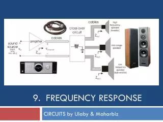
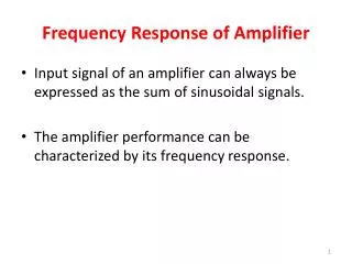
Variable-Frequency Response Analysis • As an extension of AC analysis, we now vary the frequency and observe the circuit behavior • Graphical display of frequency dependent circuit behavior can be very useful Frequency Response of an Audio Amplifier
Frequency Response of a Resistor • Consider the frequency dependent impedance of the resistor, inductor and capacitor circuit elements • Resistor (R): ZR = R 0° • So the magnitude and phase angle of the resistor impedance are constant, such that plotting them versus frequency yields R Magnitude of ZR () Phase of ZR (°) 0° Frequency Frequency
Frequency Response of an Inductor • Inductor (L): ZL = L 90° • The phase angle of the inductor impedance is a constant 90°, but the magnitude of the inductor impedance is directly proportional to the frequency. Plotting them vs. frequency yields (note that the inductor appears as a shortcircuit at dc) 90° Magnitude of ZL () Phase of ZL (°) Frequency Frequency
Frequency Response of a Capacitor • Capacitor (C): ZC = 1/(C)–90° • The phase angle of the capacitor impedance is –90°, but the magnitude of the inductor impedance is inversely proportional to the frequency. Plotting both vs. frequency yields (note that the capacitor acts as an open circuit at dc) Magnitude of ZC () Phase of ZC (°) -90° Frequency Frequency
Poles and Zeros • The transfer function is a ratio of polynomials • The roots of the numerator, N(s), are called the zeros since they cause the transfer function H(s) to become zero, i.e., H(zi)=0 • The roots of the denominator, D(s), are called the poles and they cause the transfer function H(s) to become infinity, i.e., H(pi)=
vr(t) i(t) + – R + + – vc(t) C – vl(t) – + L RLC Resonance Circuits • The denominator of the transfer function is known as the characteristic equation • To find the poles, we solve : which has two roots: s1 and s2
RLC Resonance Circuits - Resonance Frequency BW - BW=bandwidth
Quality Factor (Q) • The quality factor is a measure of the sharpness of the resonance peak; the larger the Q value, the sharper the peak, where BW=bandwidth • An energy analysis of a RLC circuit provides a basic definition of the quality factor (Q) that is used across engineering disciplines, specifically
Bandwidth (BW) • The bandwidth (BW) is the difference between the two half-power frequencies BW = ωHI – ωLO = 0 / Q • Hence, a high-Q circuit has a small bandwidth • Note that: 02 = ωLO ωHI
Quality Factor: RLC Circuits • For a series RLC circuit the quality factor is • For a parallel RLC circuit, the quality factor is
Class Examples • Drill Problems P9-3, P9-4, P9-5