Download
1 / 28
280 likes | 376 Vues
Learn about digital circuits, advantages and limitations, history of computing, design hierarchy, components of a digital computer, analog vs digital systems, and popular applications. Explore the evolution of Intel microprocessors, digital logic families, and more.

E N D
Chapter 1: Introduction Digital Logics and Circuits 04-710-201
04-740-201วงจรดิจิตอลลอจิก 3(2-1-3)04-740-201วงจรดิจิตอลลอจิก 3(2-1-3) Digital Logics and Circuits วิชาบังคับก่อน : - ระบบจำนวนและรหัสการแปลงฐานการแทนเลขฐานสิบด้วยเลขฐานสองแบบไม่มีเครื่องหมายแบบมีเครื่องหมายการบวกลบคูณหารพีชคณิตบูลีนผังคาร์โนห์การออกแบบการจัดกลุ่มได้แก่วงจรแปลงรหัสวงจรถอดรหัสวงจรเช้ารหัสวงจรเปรียบเทียบวงจรมัลติเพล็กเซอร์วงจรดีมัลติเพล็กเซอร์วงจรบวกวงจรลบการออกแบบวงจรลำดับเช่นวงจรรีจิสเตอร์วงจรชิฟท์รีจิสเตอร์วงจรนับแบบริปเปิ้ลวงจรนับแบบซิงโครนัส
DIGITAL ELECTRONICS • WHAT IS A DIGITAL CIRCUIT? • WHERE ARE DIGITAL CIRCUITS USED? • WHY USE DIGITAL CIRCUITS? • HOW DO YOU MAKE A DIGITAL SIGNAL? • HOW DO YOU TEST FOR A DIGITAL SIGNAL?
Advantages of Digital Techniques • Digital systems are easier to design. • Information storage is easy. • Accuracy and precision are greater. • Operation can be programmed. • Digital circuits are less affected by noise. • More digital circuitry can be fabricated on IC chips. • Computer compatibility, memory, ease of use, simplicity of design, accuracy, and stability. Limitation of digital circuits • Most “real-world” events are analog in nature. • Analog processing is usually simpler and faster.
SUMMARY • Analog signals vary gradually and continuously, while digital levels usually referred to as LOW and HIGH. • Most modern electronics equipment contain both analog and digital circuitry. • Logic levels are different for various digital logic families, such as TTL and CMOS. • Digital circuits have become very popular because of the availability of low-cost digital ICs. • Bistable, monostable, and astable multivibrators are used to generate digital signals. • Logic level indicators may take the form of simple LED and resistor circuits, volt-meters, or logic probes.
Digital Systems - Design Hierarchy (1) • System level - Register level - Gate level - Transistor and physical design level • System level: Black box specification. • Register level: Collection of registers.
Digital Systems - Design Hierarchy (2) • Gate level: Collection of logic gates.
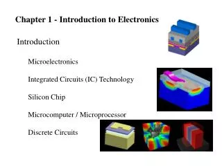
Digital Systems - Design Hierarchy (3) Transistor and physical design level: Each logic gate is implemented by a lower-level transistor circuit. Electronic Technologies:
Organization of a Digital Computer - Four Major Components • Control unit: Follows the stored list of instructions and supervises the flow of information among other components. • Arithmetic/logic unit (ALU): Performs various operations. • Memory unit: Stores programs, input, output, and intermediate data. • I/O devices: Printers, monitors, keyboard, etc.
Organization of a Digital Computer - Instruction Cycle • Fetch the next instruction into the control unit. • Decode the instruction. • Fetch the operands from memory or input devices. • Perform the operation. • Store the results in the memory (or send the results to an output device).
Analog v.s. DigitalDefinitions: • Analog Systems: process time-varying signals that can take on any value across a continuous range of voltage, current, or other metric. • Digital Systems: also deal with time-varying signals but they treat these signals as “NON” time-varying, which these signals are modeled as only one of two discrete values: 0 or 1 (LOW or HIGH)
Audio recording: magnetic tape => CD Automobile carburetors: “analog” mechanical leakage => microprocessor control Telephone system: “pure” analog system => digital conversion for routing in central office Traffic lights: electromechanical timers => computer control Movie effects: miniature clay models => computer graphics Analog v.s. DigitalApplications:
Why digital system is popular. • Reproducibility of results: same input => same output • Ease of design: no special math skills are required. • Flexibility and functionality: logical steps in space and time • Programmability: programmable hardware, i.e. PLD • Speed: responded time < 10 nanosecond • Economy: small-sized devices, e.g. IC • Steadily advancing technology: better performance chips each year
i/p1 i/p1 o/p i/p o/p o/p i/p2 i/p2 Digital Devices • Gate: the most basic digital device, which has one or more inputs and produces an output as a function of its currents input(s). OR NOT AND NOT gate: output = 0 if input = 1, output = 1 if input = 0 AND gate: output = 1 if all input = 1, otherwise output = 0 OR gate: output = 0 if all input = 0, otherwise output = 1
input output#1 output#2 clock Digital Devices (Continued) • Flip-Flop: is a device that can store its output or state, which is either 0 or 1. State can be changed by a certain pattern of “clock” input and “control” input. For example, D flip-flop: If input = 1 and clock is set, then output#1 = 1, output#2 = 0 If input = 0 and clock is set, then output#1 = 0, output#2 = 1 Note: Details about flip-flops will be discussed in the later chapters.
Combinational v.s. Sequential circuits • Combinational circuit: its output depends only on the current input combination. • Sequential circuit: output of the circuit depends on its current input and past sequence of inputs • Gate => combinational circuit • Flip-flop => sequential circuit
Electronics Aspects of Digital Design Digital Abstraction: allows analog behavior to be ignored in most cases, so circuits can be modeled as if they really did process 0 and 1. Noise margin: the difference between input and output ranges. It can prevent the real circuit from being corrupted by noise in some extend.
Software Aspects of Digital Design • Long before: software tools was not necessary. Only plastic template is enough. • Now: Computer-Aided Design (CAD) tools are playing more and more important roles. It can improve the quality of designs in the sense of correctness and designer’s productivity.
Software Aspects of Digital Design (Continued)Examples of CAD tools • Schematic Entry: Visio • Simulators: e.g. OrCAD • Hardware Description Language (HDL) used to specify particular digital devices from individual function modules (e.g. NOT gate) up to large digital systems (e.g. microprocessors) • HDL compilers, simulators, and synthesis tools
Integrated Circuits • Die: small sections of fabricated wafer (silicon plate). • Integrated Circuit: or IC is a collection of one or more gates, which are fabricated on a single silicon chip. => IC = die + package • SSI: small-scale integration => 1 – 20 gates, e.g. gates and flip-flops. • Usually, SSI IC come in a 14-pin dual in-line-pin (DIP) package.
Integrated Circuits (Continued) • Examples of 14-pin, 20-pin, and 28-pin DIP • Pin diagrams of SSI IC in some of 7400-series family.
Integrated Circuits (Continued) • MSI: medium-scale integration => 20 – 200 gates, e.g. decoder, register, counter, etc. • LSI: Large-scale integration => 200 – 200,000 gates, e.g. small memory, microprocessors, programmable logic devices, etc. • VLSI: Very large-scale integration => over 1,000,000 transistors (not number of gates), e.g. modern memory, microprocessors, etc. • What is the number of transistors in Pentium-III processor?
Programmable Logic Devices • Programmable Logic Arrays (PLAs): two-level structure of AND and OR gates • PLA = Programmable Array Logic (PAL) devices = Programmable Logic Devices (PLDs) => MSI • CPLD = Complex PLD => LSI – VLSI • Field-Programmable Gate Array (FPGA)
CPLD: a collection of PLDs, which the interconnection between each PLD module can be specified FPGA: a collection of smaller individual logic blocks, providing a large and distributed interconnection structure. Programmable Logic Devices (Continued)
Application-Specific ICsAdvantage v.s. Disadvantage • Application-Specific ICs or ASICs are also called semi-custom IC. They are used in particular, limited applications, e.g. microprocessors in mobile phones, MP3 decoders, etc. • Advantages: • reducing chip count • reducing physical size • lower power consumption • higher performance • Disadvantages: • specific/small markets • high NRE => expensive
Application-Specific ICs (Continued)Nonrecurring Engineering • NRE: nonrecurring engineering => initial cost, e.g. cost for: • designing the internal structure of the chip • creating tooling such as the metal masks for manufacturing the chip • developing tests for the manufactured chips • a few sample chips • In order to reduce NRE charges, standard cells are used in ASIC design. For example, standard cells are decoders, registers, counters, memory, microprocessors, and others. Usually, custom cells are created only if absolutely necessary.
Application-Specific ICs (Continued)Gate Array • Gate array: is an IC whose internal structure is an array of gates whose interconnection are initially unspecified. • Logic designer has to specify gate types and interconnection in high-level functions (same as standard cells). This specification will be converted into low-level design by software. • Advantages: faster in design, lower NRE • Disadvantages: 25% or more in chip cost, standard functions only (same as standard cells) => can’t build custom cells