Download
1 / 33
360 likes | 590 Vues
Transfer Function Analysis Of EM Shielded Enclosures. W. Michael King Systems Design Advisor www.SystemsEMC.com. Rev. 7/19/04. IEEE/EMC 2004 –Transfer Functions Analysis of EM Shielded Enclosures – All rights reserved.

E N D
Transfer Function AnalysisOfEM Shielded Enclosures W. Michael King Systems Design Advisor www.SystemsEMC.com Rev. 7/19/04 IEEE/EMC 2004 –Transfer Functions Analysis of EM Shielded Enclosures – All rights reserved
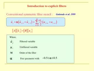
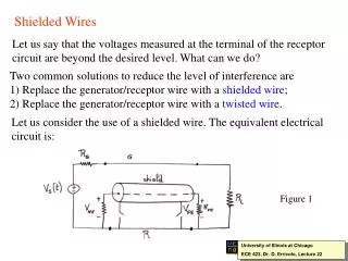
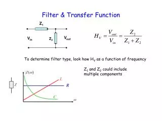
Prior to discussion of what occurs when currents propagate onto and within EM shielded enclosures (which are characterized by conducted impedances) it is useful to recall the concepts of the EM wave impedance structures as the sources of current excitation.
Observing The Impedance Structures of EM Waves #1 Graphics from “EMCT: Electromagnetic Compatibility Tutorial” Used with permission from W. Michael King, E. Pavlu, and Elliott Laboratories
Observing The Impedance Structures of EM Waves #2 Graphic from “EMCT: Electromagnetic Compatibility Tutorial” Used with permission from W. Michael King, E. Pavlu, and Elliott Laboratories
Evaluating EM Wave Structures To Practical Distances Graphics from “EMCT: Electromagnetic Compatibility Tutorial” Used with permission from W. Michael King, E. Pavlu, and Elliott Laboratories
Reviewing The Applied Currents Into Shield Boundaries Review of interposing media impedances Graphics from “EMCT: Electromagnetic Compatibility Tutorial” Used with permission from W. Michael King, E. Pavlu, and Elliott Laboratories
What Occurs In “Real” EM Shielded Enclosures….. …..Once the Current As Sourced From EM WavesConducts Into And Through The Enclosure Structure?
Infinite Sheet with Aperture • Incident EM fields cause currents I1 to flow on sheet • Current flows around small aperture inducing voltage V due to resistance of a skin depth of metal and inductance and capacitance of U-shaped path • Voltage V causes current I2 to flow in local areas on other side inducing electric field E2 and magnetic field H2 (not shown) • E2 maximum at center of slot, H2 (Magnetic field) maximum at ends of slot.
Apertures In Products Form “Arrays” Graphics from “EMCT: Electromagnetic Compatibility Tutorial” Used with permission from W. Michael King, E. Pavlu, and Elliott Laboratories
Small Enclosure Behind Aperture • Incident fields, external current I1 and Voltage V similar to Infinite Sheet with Aperture (page 8) • Enclosure reduces impedance across rear of aperture and increases I2 • E2 smaller than for Infinite Sheet • I2 larger than for Infinite Sheet
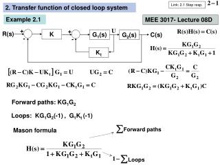
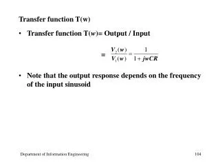
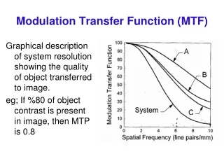
Impedance of Gasket Segments Impedance of Gasket Segments with 7” spacing as measured by Transfer Impedance Test Fixture • Seven (7) inches is approximately ¼ wave length of 470 MHz. • The measured impedance at 470 MHz was 22 Ohms. • The voltage can be estimated (through extrapolation) across a slot that is ¼ wave length long. • The contents of the graph can also be used to estimate the voltage across any slots or holes as a function of frequency (generated by the slot or hole) and induced field strength.
Maintenance Cover Relatively high levels of shielding can be obtained without the use of EMI gaskets. Gaskets can be cost effective by reducing the number of screws needed to obtain the required shielding. Gaskets are generally required (or very cost effective) in shielding for frequencies of 100 MHz and higher. Corrosion control should be an important consideration in the selection of the EMI gasket.
Air Vent Filters • Air Vent Filters are used successfully to allow air to penetrate an enclosure and attenuate the EM Waves • The materials used for this purpose are (1) conductive screening, (2) perforated metal, and (3) honeycomb panels • Honeycomb panels are often preferred because of the high level of shielding and small resistance to air flow • The panels are manufactured from brass, steel and copper foils, which are soldered, welded or brazed together, and offer excellent levels of shielding (up to 140 dB) • Aluminum honeycomb panels are often used because of the low cost for the aluminum paneling. • The level of shielding offered by the basic aluminum honeycomb panels can vary from very poor (less than 20 dB) to as much as 70 dB. • Non-conductive epoxy is used in manufacturing to hold the foil segments together. • The basic conductivity across the epoxy joints is obtained through incidental bridging of the epoxy, which occurs when the honeycomb loafs are cut into panels.
Shielding of Aluminum Honeycomb Panels • The shielding offered by aluminum honeycomb panels is a result of the conductivity which occurs across the epoxy joint of the foils used to make the panels. • The plating (and processing) used to enhance the shielding offered by basic Aluminum Panels is as follows: 1. Electroless Nickel plating (.002 inches thick) • The panels offer as much shielding as the soldered or welded panels. However, the cost to plate is extremely high. 2. Tin plating of the panels • The process can add to the shielding supplied by the basic panel. However, the cleaning process used during the plating process can significantly reduce the level of shielding. 3. Chemical Film plating of the panels • The use of the plating cannot improve the shielding and can result in a significant loss of shielding due to the cleaning process used in plating the filters. 4. Patented Blending Process • The blending process supplies a high reliable level of shielding to the basic panel where the 2 panel versions offer as much shielding as the soldered or welded panels.
Shielding Effectiveness Test Results of Shielded Aluminum Honeycomb Panels • The level of shielding offered by aluminum honeycomb panel material is a function of the conductivity across the epoxy joint used to hold the panel foil segments together. • The data below illustrates the level of shielding offered by 1/8 inch cell by ¼ inch thick honeycomb panels, and a microscopic picture of the foil to foil joint of the panel under test. Epoxy Joint Incidental Contact Points Incidental contact points across the epoxy joint are created when the honeycomb is cut into panels. Basic Aluminum Honeycomb Panel
Shielding Effectiveness Test Results of Shielded Aluminum Honeycomb Panels Tin Plated Aluminum Honeycomb Panels The tin plating process can remove the incidental contact points. Blending creates a continuous conductive path across the epoxy joint. Blended Aluminum Honeycomb Panel
Shielding Effectiveness Test Results of Shielded Aluminum Honeycomb Panels Solder provides excellent conductivity between the brass foils. Brass Honeycomb Panel The nickel plating totally bridges the epoxy joint. Electroless Nickel Plated Honeycomb Panel (.002 inches thick)
Performance Approximation of Waveguides “In Cutoff” fc = 5910/W where, fc = cutoff frequency in megahertz (MHz) W = largest inside dimension of the rectangular aperture of the waveguide (in inches) fc = 6920/W where, fc = cutoff frequency in megahertz (MHz) W = inside diameter (in inches) of the circular waveguide Graphics from “EMCT: Electromagnetic Compatibility Tutorial” Used with permission from W. Michael King, E. Pavlu, and Elliott Laboratories
Power and Signal Line Penetration of Enclosure • Power and signal lines brought into a system are usually protected by shields on the cables or terminated into an EMI filter at the penetration. • When EMI gaskets are used to reference the shields or filters to the equipment chassis, care must be exercised to illuminate the loss of the EM bond due to corrosion. • The amount of shielding provided by a shield in a cable can vary as much as 30 dB depending upon the conductivity of the gasket used to reference the shield to the equipment chassis. • When the lines are not shielded or terminated into EMI filters, extreme care must be exercised to ensure EM coupling to and from the wires is not excessive.
Equipment Box with Shielded Cables Gaps except at screws (rubber gasket or anodized aluminum surface) • This design (without gasket) induces large magnetic fields H2 due to concentrating the current in the bolts and large electric field E2 due to the voltage drop along the inductance and contact resistance of the bolts.
Shielding Materials For Optically Transparent Sheet Materials Copper Sheeting with etched square holes: Often used on Airplane windshields for EMI and Lightning protection. Screening: Usually .001 thick wire on .010 to .020 inch spacing. It is recommended to fuse the wires together with tin plating. Conductive coatings: Gold, Indium, and Indium Tin Oxide are the usual coating materials.
Termination of Optically Transparent Sheet Materials • Best Option: • The EMI shield is protected on both sides with glass. • The EM bond between the shield and chassis is positive and inexpensive to obtain. EMI Shield Glass Chassis EMI Gasket • GoodOption: • The EMI shield is inside the enclosure and not subject to scratching & abrasive cleaning. • The EM bonding block will require fairly close tolerance and is relatively expensive. EM bonding block EMI Shield Glass Chassis EMI Gaskets
Termination of Conductive Glass • Poor Option: • For Electrostatic Discharge Only. • The coating can be subject to scratching & abrasive cleaning causing a loss of shielding. EMI Shield Glass Chassis EMI Gasket • Not Recommended: • The EMI screen shielding material is referenced to chassis using silver epoxy. • The silver can cause pitting of the chassis and loss of shielding due to galvanic corrosion. Glass EMI Shield Silver Epoxy Chassis EMI Gasket
Loss of Surface Conductivity Due to Oxidation Contact Resistance (Average of Several Test Sites) Results of a test conducted by IBM and presented by G. Roessler of Technit in a paper entitled "Corrosion and the EMI / RFI Knitted Wire Mesh Gasket."
Loss of Surface Conductivity Due to Oxidation Resistance Measurements of Selected Materials Results of testing extracted from paper “Corrosion Control in EMI Design” by Earl Grosshart of Boeing Aerospace Company.
Material Compatibility Extracted from SAE Standard: “SAE, ARP-1481" A - Compatible D - Compatible in controlled temperature and humidity only. C - Requires sealing if exposed to humid environment. E - Requires sealing regardless of exposure. X - Not usable.
EMF Potentials: Key To Stability Graphic from “EMCT: Electromagnetic Compatibility Tutorial” Used with permission from W. Michael King, E. Pavlu, and Elliott Laboratories
Galvanic Corrosion of Mesh Gasket • Galvanic Corrosion caused by Tin Plated Mesh Gasket against Aluminum MCGS Frame. System in Field Environment for 6 months. Photograph by Rockwell International.
Loss of Conductivity Due to Corrosion • Silver Filled Elastomeric Gasket loses conductivity due to Sulfer Sulfide Coating of Silver Particles • Transfer Impedance Test Data of EMI Gaskets Against Chemical Film Plated Aluminum New Aged 1 Year(stored on shelf) Silver Filled Silicon Elastomer30 lb. force Reading taken by Peter Madle at TRW and reported at 1978 IEEE EMC Symposium Atlanta, GA.
Adequate compression is essential! Graphics from “EMCT: Electromagnetic Compatibility Tutorial” Used with permission from W. Michael King, E. Pavlu, and Elliott Laboratories
Summary Recognition of the fundamental processes of EM wave structures is essential background, required to evaluate enclosure performance. Shielding mechanisms are found in the form of responses to conducted currents that are propagated in the enclosure materials and structures, as sourced from EM waves. Shielding performance of EM shielded enclosures is related to the transfer functions and impedance structures of the materials and construction. Impedances of seams, gaps, and apertures typically constitute the limitation of performance of EM shielded enclosures, assuming appropriate selection of material. Stability of performance for gaps and seams is dramatically impacted by compression pressures and EMF compatibility.
Selected References • King, Michael W., EMCT: High Speed Design Tutorial (ISBN 0-7381-3340-X), Module 3, Sections A and B, Published by Elliott Laboratories, Sunnyvale California, August, 2002. • Archambeault, Bruce and Thibeau, Richard “Effects of Corrosion on the Electrical Properties of Conducted Finishes for EMI Shielding,” 1989 IEEE, EMC Symposium, Denver, CO. • Denny, Hugh W. & Shouse, Kenneth R., EMI “Shielding of Conductive Gaskets in Corrosive Environments,” 1990 IEEE, EMC Symposium, Washington D.C. • Groshart, E., “Corrosion Control in EMI Design,” 1975 IEEE, EMC Symposium, Texas. • Kunkel, George, “Corrosion Effects on Field Penetration through Apertures,” 1978 IEEE, EMC Symposium, Atlanta, Georgia. • Kunkel, George, “Corrosion Effects on EMI Gasketed Joints” 1979 IEEE, EMC Symposium, San Diego, CA. • Lachmar, E.B. “Corrosion of MGCS Frame at EMI Gasket Interfaces” Rockwell International Internal Letter, April 12, 1983. • Lin, W.W; Reilly, J.J., Lee, H.J. & Brown, R.J. “Preliminary Corrosion Study of EMI Gaskets for Avionic Systems,” Naval Air Development Center, September 1987. • Reinhold Publishing Corporation “CORROSION, Special Report,” M/DE Magazine, January 1963. • Roesseler, George D., “Corrosion and the EMI/RFI Knitted Wire Mesh Gasket,” Frequency Technology, March 1969. • Cain, Bruce L., “EMI/RFI Gasketing for Tactical Shielded Door Seam Applications”, U.S. Army Construction Engineering Research Laboratory.
End of Presentation Please close window to go back to CD or click to go back to the First Presentation.