4 bit Versatile CMOS Rate Multiplier
4 bit Versatile CMOS Rate Multiplier. Hardik Parikh Akshay Bhat Alex Jose Swastick Biswas Advisor: Dave Parent DATE: 05/11/2005. Agenda. Abstract Introduction What is a Rate Multiplier and applications Cumulative adder Principle Improvements made to make the circuit versatile

4 bit Versatile CMOS Rate Multiplier
E N D
Presentation Transcript
4 bit Versatile CMOS Rate Multiplier Hardik Parikh Akshay Bhat Alex Jose Swastick Biswas Advisor: Dave Parent DATE: 05/11/2005
Agenda • Abstract • Introduction • What is a Rate Multiplier and applications • Cumulative adder Principle • Improvements made to make the circuit versatile • Project Highlight • Project Details • Results • Cost Analysis • Conclusion
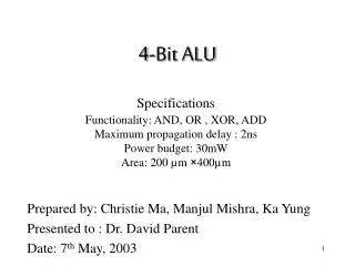
Abstract We designed a 4-bit rate multiplier that operates at 200 MHz and uses 18.9mW of Power and occupies an area of 380 x 200 mm2
Introduction • Rate Multiplier: A digital circuit that multiplies the incoming clock by a ratio to give an output pulse rate: where, P and Q are integers and P < Q This is not a frequency divider as numerator P is not one • Application: * Arithmetic & Mathematic Functional generation * PCM systems * Motor Control Systems * Vector Generation & Interpolation * Frequency Synthesizer
Introduction Clock Reset P (Clock) D Register Q Full Adder Capacity = Q Cumulative Adder Principle P
Introduction Clock Reset P (Clock) 4bitD Register Q c_out 4 bit Adder (CLA) D select 4 bit Multiplexer (2:1) 24 – Q + P Adder (CLA) Cin = 1 P 1’s Complement Q
Project highlight • Programmable rates that broaden the application area considerably • High speed implementation through Carry look ahead adders • Optimally spaced output pulse distribution • Cascadable in multipliers of 4 bits • Most of the standard industry chips are BCD rate multipliers. This rate multiplier is more versatile as the denominator Q is programmable.
Project Details Functional Verification Architecture Style Sizing, Schematics, Simulation Floor Planning Layout & Verification Post extraction simulation
Architecture Style Option 1: Standard AOI
Architecture Style Example: Carry out c4 = G3 + P3G2 + P3P2G1 + P3P2P1G0 + P3P2P1P0C0 Option 2: Using minimum transistors
Architecture Style Option 3: Combination of AOI and Boolean Gates.
Longest Path Calculation Clock Reset P (Clock) 4bitD Register Q 4 bit Adder (CLA) D 4 bit Multiplexer (2:1) Assuming that P and Q do not change Adder (CLA) Cin = 1 P 1’s Complement Q
Longest Path Calculations TP = 5 nsec / 9 = 0.555 n sec
And D ff (input) CLA 1 Mux CLA 2 D ff (input) CLA 1 Mux CLA 2 CLA 1 Mux CLA 2 D ff (input) D ff (input) CLA 1 Mux CLA 2 D ff (input) D ff (Register) D ff (Register) D ff (input) Floor Plan D ff (input) D ff (Register) D ff (Register) D ff (Sync.) D ff (input)
Layout • Features: • Vdd and Ground lines interleaved to save area • Efficient routing and negligible empty space • Approximately squarish. The 4 hours spent on floor planning was worth it!
Verification net-lists match !
Cost Analysis • Time spent on each phase of the project in man hours • Verifying logic: 10 • Schematic, sizing and verifying timing: 40 • Layout: 140 • Post extracted timing: 5
Lessons Learned • Have a rough idea of DRC rules before sizing the transistors. We underestimated the DRC minimum metal spacing only to find that the design became too tight. • Before starting layout spend time on making a floor plan • Document your design • Using Cell based design makes life easy! It reduces debug time • Time management is the key between success and failure!
Summary • This project gave us a good overview of Digital CMOS Circuit Design. • Rate-multipliers can be used for low power frequency synthesizers.
Acknowledgements • Thanks to Cadence Design Systems for the VLSI lab • Thanks to Professor Dr. Parent for his timely advice.