4-Bit Adder
4-Bit Adder. Switching and Logic Lab Standard Laboratory Exercises. Suggestions and Warnings. Read for detail and comprehension Should be able to complete within normal laboratory period. Make sure you program unused pins as tri-state inputs or you may burnout EPM7128S device on PLDT-2.

4-Bit Adder
E N D
Presentation Transcript
4-Bit Adder Switching and Logic Lab Standard Laboratory Exercises
Suggestions and Warnings • Read for detail and comprehension • Should be able to complete within normal laboratory period. • Make sure you program unused pins as tri-state inputs or you may burnout EPM7128S device on PLDT-2.
4-Bit Adder • Project 1 • Adder4 as structural VHDL • FullAdder as dataflow VHDL • VHDL based project • Project 2 • LPM_ADD_SUB • BDF based project
A B Cout Cin S FullAdder VHDL
Full- Adder Hierarchical Design Y[3] X[3] Y[2] X[2] Y[1] X[1] Y[0] X[0] Adder4 U04 U03 U02 U01 C R[4] R[3] R[2] R[1] R[0]
Adder4 Structural VHDL Entity Component Declaration Component Instantiation
Full- Adder U01 Full- Adder U02 Full- Adder U03 Full- Adder U04 Components Within Structure Y[3] X[3] Y[2] X[2] Y[1] X[1] Y[0] X[0] Adder4 C A R R Y [2] C A R R Y [0] C A R R Y [1] C R[4] R[3] R[2] R[1] R[0]
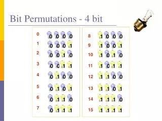
Simulation Waveforms • 4 + 4 + 1 inputs = 9 inputs • 29 = 512 combination • 512 combinations x 100 ns = 51200 ns or 51.2 us as Ending Time • X[0] count value as 100 ns x 1,
Simulation Waveforms • X[1] as 100 ns x 2, • X[2] as 100 ns x 4, • X[3] as 100 ns x 8, • Y[0] as 100 ns x 16, • Y[1] as 100 ns x 32, • Y[2] as 100 ns x 64, • Y[3] as 100 ns x 128,
Simulation Waveforms • And C as 100 ns x 256. • Group X[0] to X[3] and Y[0] to Y[3]. • Change property to unsigned decimal for X, Y, and R for easier checking.
Adder4 by BDF and LPM Place Adder4.bdf in different folder than Adder4.vhd Note signal names
Create VHDL Quartus Sandwich Adder4.BDF LPM_ADD_SUB.VHD LPM_ADD_SUB.TDF AHDL
Simulation Without Carry-In (Cin = 0) With Carry-In (Cin = 1)
Unused Pins as Tri-State Inputs • Select “Assignments” • Select “Device” • Select “Device & Pin Options” • Select “As inputs, tri-stated” • OK
ADDER4.QPF Adder4.QPF FullAdder.VHD LPM_ADD_SUB0.VHD Adder4.BDF Adder4.BDF Each Task In Its Own Folder Task 1 Task 2
Pre-Lab • Introduction to Comparators • Iterative Network Node Truth Table • Derive Additional Test Cases • Derive Boolean Function