4-Bit Arithmetic Logic Unit (ALU) with Carry Look Ahead Adder
220 likes | 2.24k Vues
4-Bit Arithmetic Logic Unit (ALU) with Carry Look Ahead Adder. Keli Wu Eng Boon Chong Li Li Chun Sum Yeung Advisor: David Parent May 2005. Agenda. Abstract Specifications Introduction ALU Operations Design Flow Design Issues Schematics Lessons Learned Simulation Results

4-Bit Arithmetic Logic Unit (ALU) with Carry Look Ahead Adder
E N D
Presentation Transcript
4-Bit Arithmetic Logic Unit (ALU)withCarry Look Ahead Adder Keli Wu Eng Boon Chong Li Li Chun Sum Yeung Advisor: David Parent May 2005
Agenda • Abstract • Specifications • Introduction • ALU Operations • Design Flow • Design Issues • Schematics • Lessons Learned • Simulation Results • Conclusions
Abstract • Successfully designed a 4-bit ALU with Carry Look Ahead Adder by using Cadence CAD tools. The entire project is designed towards AMI06 (0.6mm) process specification. The design has successfully passed DRC and LVS, as well as met the desired 200MHz clock speed, power and area constraints.
4-bit ALU Specifications The designed ALU meets the following specifications: • Able to perform 4 Logic Operations and 8 Arithmetic Operations • Operating Frequency: 200MHz • Output DFF must be able to drive 30fF.
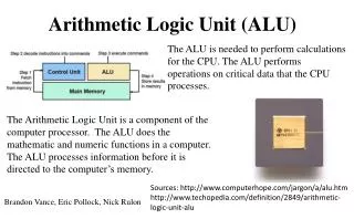
Introduction • An Arithmetic Logic Unit (ALU) is the fundamental unit of any computing system. It is portion of the digital computer hardware in which arithmetic and logic operations are performed • The ALU designed is able to handle two 4-bit inputs to produce a required output based on the output selector line. • The complete list of the possible outputs functions are as listed in the following tables.
Design Flows • Create Schematics and layouts for Nand, Nor, Xor, Carry Generators, Adder, flip-flop, and Mux in the Cadence tool. • Test the schematics logic of each modules by using NCVerilog. • Cascaded the above single bit parts to form 4-bit parts. • Assembled all the 4-bit parts together. • Run the DRC, extracted and LVS check to verify the design. • Analyzed the circuit power and timing by using Affirma.
Design Issues • Implementation of long Boolean expressions for Carry Generators. Breakdown logic level instead of using AOI. • 21 logic levels, requires larger devices for faster propagation delay per logic level. • Transistors are sized to have the same dimensions so that they fit together nicely. • The compact layout requires careful consideration for signal routing.
Logic Simulation Input A: 1000 Input B: 1T00
Power Simulation • Power = 18.7 mW (Only the longest path, about 15% • of the circuit, is switching.)
Lessons Learned • Don’t route in Poly • Fix the LVS Error • Use hierarchy approach • Optimize transistor size to meet specification. • Basic power routing.
Conclusions • Our project has 1176 transistors and 21 terminals. • The area of our design is approximately 390mm X 360mm. • The power is approximately 131mW. • The circuit can operate up to 250MHz.
Acknowledgements • Thanks to professor David Parent for his guidance and help throughout the project. • Thanks to Cadence Design Systems for the VLSI Lab.