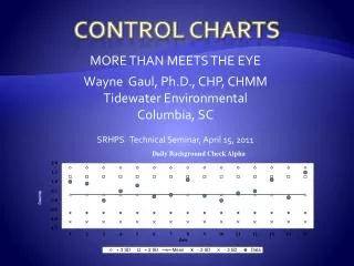
Control Charts
Control Charts. EE/MatE167 David W. Parent. Control Chart Design Flow. Make decisions to prepare for control chart construction Possible Objectives Choose the variable Decide on basis of subgroup Choose size and frequency of subgroups Set the data collection form

Control Charts
E N D
Presentation Transcript
Control Charts EE/MatE167 David W. Parent
Control Chart Design Flow • Make decisions to prepare for control chart construction • Possible Objectives • Choose the variable • Decide on basis of subgroup • Choose size and frequency of subgroups • Set the data collection form • Determine method of measurement
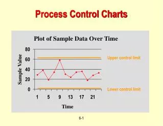
Control Chart Design Flow II. Start the control charts • Make chart and record data • Calculate Xbar and R for each subgroup • Plot Xbar and R
Control Chart Design Flow III. Determine trial control limits • Decide on how many subgroups are required to calculate the limits • Calculate trial control limits • Plot the central lines and limits
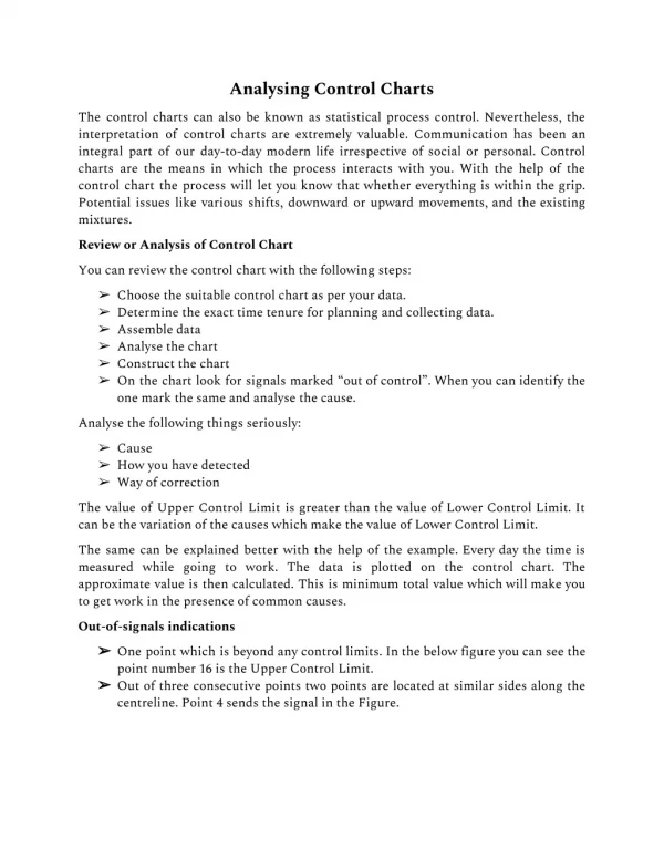
Control Chart Design Flow IV. Draw preliminary conclusions • Decide whether in control or out • Interpretation • Discuss relationship between out of control processes and specification limits • Suggest actions
Control Chart Design Flow V. Continue to use the charts • Revise central lines and limits • Sort lots • Decide on an action about a process • Acceptance inspection • Verify specifications
I-A Objectives • Gather data • to verify specifications • verify production procedures • verify inspection procedures • justify current decisions • justify whether to hunt for problems • Learn control charts
I-B Variable • Gather data that can • be measured in numbers • that can be used to save money or improve process
I-C sub group • Choose subgroups that • are as homogenous as possible if you are trying to detect shits in the process mean • are not homogeneous if acceptance testing
I-D Size of subgroup • 4 is thought to be ideal • 5 is easy to calculate • gets all area of a wafer • try to minimize variation in subgroup • 2 or 3 if it is expensive • 10-20 if we need a large sensitivity of shifts in the mean and standard deviation
Forms and method of measurements • Forms • We will try to develop standard excell sheets so groups can share data • Measurement • We have detailed instructions on how to use equipment
Example • EE129 process • Assume we are making simple current mirrors.
I-A Objectives • What are the possible objectives? • Or what are our main problems in EE/MatE129? • Currently we just make transistors to learn about processing, we don’t make them for a given application • We want to change this so EE students can design circuits that are made in 129.
What do we need for a design environment? • A process that is in control • An idea of what specification limits the circuits designers can expect
More possible objectives (Current Decisions) • Currently in 129 there is a lot of time spent measuring oxide thicknesses for etching, lab often goes over this time or students have to come back to do it. • We want to reduce time spent inspecting! • Currently in the 129 process there is 8 microns of overlap to prevent device failures to to alignment • This caused the S/D area to be large • This causes device to be big, which limits how many devices we can put a on chip • More leakage • We need to verify this design rule!
More possible objectives • Since we have not been doing control charts, we do not know if we have a problems, so lets not hunt for any. • If we find one, we find one. • We need to learn control charts!
Choose the variable? • Substrate doping • Junction capacitance • Channel width • Channel Length • VT, fixed oxide charge • gamma • lambda (50 other bsim4 parameters) • Oxide breakdown • Junction Breakdown • Electromigration max current density • Metal1 Ndiff capacitance • What are the variables? • Wafer thickness • Wafer resistivity • Field oxide thickness • SOG Thickness • Gate oxide thickness • Diffusion resistivity • Junction depth • Contact resistivity • Metal height • Metal resistivity • mobility • KN
There are 21 Variables in this simple 4 mask process! • We need to narrow this number down. • We need to compare the variables in terms of cost to measure, effect on the process, benefit we get from monitoring a particular variable. • Where do we start? • We go back to our product and the first order equations.
If the W and L variation track, we can expect at least a 4% variation. If they don’t track 50%! Good Layout can minimize this
Resistor Pass-through
VT • VT changes with VSB This will cause trouble later.
Mobility • Mobility changes with electric field • The constant KNP, is never constant • We use an average
l • This is due to the channel length narrowing. • The reversed biased diode’s depletion region gets bigger with VDS, and thus the length of the channel gets smaller, and thus the ID goes up.
What does the circuit design engineer control? • How big W and L are. • How the wires are connected. • This does not sound like much is it is a lot.
What does the process design engineer control? • Tox • Na • Junction Depth • Qi (kind of)
Will still need to decide the variable! • We can see that gate oxide thickness is very important. • It is easily measured • It is measured early in the process
Choose the subgroup • We need to know how the oxide varies on the wafer, so we need to take 5 measurements on each wafer. • The lots are not independent on wafer or in a single run of 50 wafers • We still need to know if all wafers are within a spec limit so we need to measure each wafer in the batch • After one run we can see trends and maybe we can take one ready per wafer or even every other wafer. • We will choose to use all the readings from the center of each wafer. • Since this will mean a subgroup of 10, we should use the Xbar, s (standard deviation) chart. We also want to use the Xbar s because we our product is analog and we need to be more sensitive to problems.
Preliminary Data • There seems to be a trend with top and center, but the others are mixed. • To minimize the variation within the subgroup we should take the top measurement from each wafer for the control chart. (We still need the other data for other things.)