Download
1 / 26
390 likes | 662 Vues
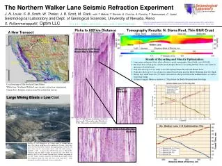
Seismic refraction interpretation is a vital method for mapping geological structures using travel times of head waves. This technique applies to 2 and 3-layer refraction cases, where head waves travel through different layers with varying velocities. Key objectives include measuring arrival times as a function of source-receiver distance, allowing the determination of refractor depths and velocities. The importance of critical distance, crossover distance, and various shooting methods are described, alongside practical applications in real-world scenarios such as locating trapped miners and finding sinkholes.

E N D
Seismic Refraction Interpretation 2 and 3 Layers Case
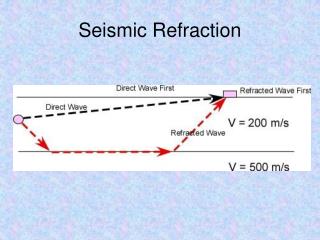
Refraction SeismologyDefinition A method that maps geologic structure using the travel times of head waves. Ground surface
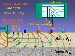
Refraction SeismologyHead Waves Head waves are elastic waves that enter a high-velocity medium (refractor) near the critical angle and travel in the high-velocity medium nearly parallel to the refractor surface before returning to the surface of the Earth. S R Layer 1 Velocity = V1 ic Layer 2 Velocity = V2 V2 > V1
Refraction SeismologyObjectives The objective in refraction surveys is to measure the arrival times of head waves as a function of source-receiver distance so that the depth to and velocity of the refractors in which they traveled can be determined. T X
2 Layer Case x S R Layer 1 Velocity = V1 Z ic ic A B Layer 2 Velocity = V2 V2 > V1 Refracted time from S to R is given by
2 Layer Case Straight line equation A is the slope B is intercept with vertical axis at x = 0
Traveltime Curve Refracted waves Direct waves Time (s) Offset (m)
Depth to Refractor to is the intercept time
3 Layer Case Horizontal Refractor S R x Layer 1 Velocity = V1 1 Z1 A D Layer 2 Velocity = V2 Z2 2 B C Layer 3 Velocity = V3 V3 > V2 > V1 Refracted time from S to R is given by
Definitions Critical distance: Critical distance (xc) is the minimum horizontal distance from the shot point at which the first refracted pulse can be recorded. • Critical refraction has same travel time as reflection • Angle of reflection same as critical angle Cross-over distance: Cross-over distance (xco) is the horizontal distance from the shot point where the direct wave reaches the receiver simultaneously with the refracted wave. xco xc ic
Definitions Shot – Geophone Relation Forward shooting Reverse shooting Split shooting Offset shooting
2 Layer CaseDipping Refractor Reciprocal time Time (s) Slope=1/Vd Slope=1/Vu t1u t1d Slope=1/V1 S R Offset (m) Zd Zu A B
2 Layer CaseDipping Refractor Downdip shooting Updip shooting
2 Layer CaseDipping Refractor If is small enough so that, cos = 1 and sin = , then If is very small then
Recording Instrument (Seismograph) 120 channels Bison from 1980’s Up to 64 channels Stratavisor NZ from Geometrics 24 channels Geode from Geometrics
Receivers (Geophones) Geophones
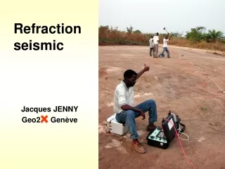
Seismic Sources (Land) Sledgehammers Find trapped miners experiment (AZ. USA) Find sinkholes (Utah, USA)
Seismic Sources (Land) Weight drop (Nevada, USA) Vibroseis Explosive
Setup a Seismic Survey Seismograph Source cable Source point Geophone cable Geophones
Picking First Arrivals Data example, Park City, UT. Profile # 1
Our First Field Test • Why? Introduction to field work • Where? Here on campus • What? 2D profile • When? • 48 Channel • 4 shots (2 forward and 2 reverse) • Targets: find layer velocity, thickness and dip • Survey layout: two perpendicular receiver lines, 24 channel each • Number of stacks and geophone interval will be determined in the field
Summary • Seismic refraction can be used to find layer velocity • Depth to refractor and its dipping can also be found • Layer velocity is equal to 1/slope • Layer thickness is found from the value of the intercept time • Layer dip can be found if the depth at two points is known