Seismic Refraction Method for Groundwater Exploration
220 likes | 413 Vues
Understand the importance of aquifer identification in groundwater hydrology and learn about the seismic refraction method for exploration. Discover how seismic waves help determine aquifer characteristics and how geophones and shock waves aid in data collection.

Seismic Refraction Method for Groundwater Exploration
E N D
Presentation Transcript
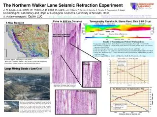
Seismic Refraction Method for Groundwater Exploration Dr. A K Rastogi Professor, Dept. of Civil Engineering I I T Bombay
Ground water is not available everywhere in the subsurface region and therefore it is very important first step in groundwater hydrology to identify the existence of aquifer in a particular area. It is only after the presence of an aquifer is established, the scheme of groundwater withdrawals can be planned,
Groundwater exploration can be divided into two major groups involving geohydrological and geophysical methods. Geophysical Methods are indirect methods which does not involve drilling Seismic Refraction is a geophysical method
The following information can be derived from the exploration using geophysical methods: 1.Depth of occurrence and thickness of aquifers. 2.Delineation of aquifer boundaries of very large groundwater basin. 3.Determination of distinctly different water bearing layers.
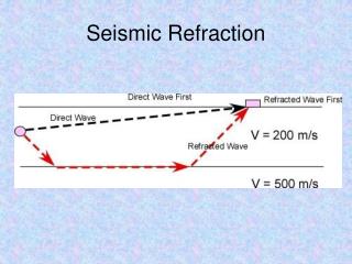
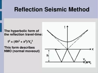
The seismic refraction method involves artificial generation of elastic waves in the ground. Elastic waves travel with different velocities in different subsurface formations (2.5-6.5 km/s in the rocks,1-2.5 km/s in sandy aquifers, and 0.31-0.61 km/s in the non aquifer overburden.) These waves behave similar to light waves while passing from one medium to another. When acoustic impedance contrast ρ1V1 ≠ ρ2V2, the elastic waves undergo changes in their directions of onward travel due to reflection and refraction and get returned to the earth surface due to refraction.
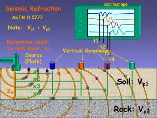
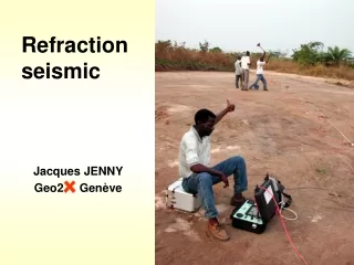
The shock waves are generally produced by exploding dynamite (about 500 gm) in a hand augured backfilled hole of about one meter depth. Sometimes, the method of hammering a thin plate placed over ground surface is also used. On the emergence of these waves after refraction from the subsurface boundary, these are detected by a suitable device called as geophones. These geophones are kept in a line at 5- 20 m interval. On receiving the elastic wave, geophones transmit electric signals. These signals are generally weak, and therefore, amplified and then recorded. Thus, the time of origin of shock waves and their first arrival on the surface either as direct waves or refracted waves (in distant geophones) are noted down in the seismic refraction.
Principle of Seismic Refraction Let A be a source on the ground surface and a seismic refractor underlies at a depth H from the source. The seismic wave reaches the point B which falls in other medium. If T is the total time for the seismic wave to travel a distance APB from low velocity medium V1 to higher velocity medium V2,
Differentiating with respect to x and making dT/dx = 0 gives Or . For the seismic refraction to take place along the inter face boundary, r = 90o, and if the corresponding angle of incidence is θ,
t10 t8 t6 t4 t2 x9 x10 x4 x8 x3 x6 x5 x7 x2 x1 Geophones Shot A D H V1 B C V2
Time of First Arrival in millisecond x9 x10 x4 x8 x3 x6 x5 x7 x2 x1 Shot Detector Distance in m
Determination of Depth to Aquifer (a) Intercept time method For direct waves For refracted waves
The slope of this segment on the travel time curve is 1/V2 and the intercept on the time axis is Therefore, the depth to the formation is given as:
(b) Cross-over distance method The cross-over distance method is another way of finding H. Since the field data do not exhibit an exact straight line fit, it is advisable to cross-check the results using other methods, such as the cross-over distance method. As both direct and refracted waves arrive at the geophone together. At less than this direct wave reaches first, at more than this refracted wave reaches first. Hence, for X= XD , TD = TR
A D E B C F Determination of the Sloping Aquifer Thickness Principle of Reverse seismic profiling is used According to this principle time for travel along ABCD is equal to the time for travel along the path DCBA
Conclusions Seismic Refraction method can be effectively used to find the depth of occurrence of the aquifer. It can find the thickness of the aquifer. It can find the angle of slope of the sloping aquifer by reverse seismic profiling. It can take care of the undulating topography which is normally present in many field situations. It can not predict about the quality water quality.