Multicycle Approach in Computer Architecture
Implementing a multicycle approach with reuse of functional units, control signals determined by step, and five execution steps for efficient processing. Learn about instruction steps, control signals, and execution cycles.


Multicycle Approach in Computer Architecture
E N D
Presentation Transcript
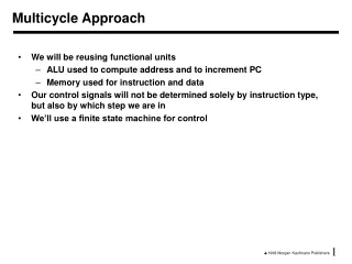
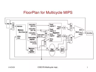
Multicycle Approach • We will be reusing functional units • ALU used to compute address and to increment PC • Memory used for instruction and data • Our control signals will not be determined solely by instruction type, but also by which step we are in • We’ll use a finite state machine for control
Multicycle Approach • Break up the instructions into steps, each step takes a cycle • balance the amount of work to be done • restrict each cycle to use only one major functional unit (ALU, memory, register file) • At the end of a cycle • store values for use in later cycles (easiest thing to do) • introduce additional “internal” registers
Five Execution Steps • Instruction Fetch • Instruction Decode and Register Fetch • Execution, Memory Address Computation, or Branch Completion • Memory Access or R-type instruction completion • Write-back step INSTRUCTIONS TAKE FROM 3 - 5 CYCLES but the cycles are shorter now
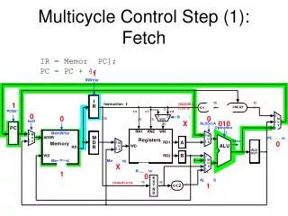
Step 1: Instruction Fetch • Use PC to get instruction and put it in the Instruction Register. • Increment the PC by 4 and put the result back in the PC. • Can be described succinctly using RTL "Register-Transfer Language" IR = Memory[PC]; PC = PC + 4;Can we figure out the values of the control signals?What is the advantage of updating the PC now?
Step 2: Instruction Decode and Register Fetch • Read registers rs and rt in case we need them • Compute the branch address in case the instruction is a branch • RTL: A = Reg[IR[25-21]]; B = Reg[IR[20-16]]; ALUOut = PC + (sign-extend(IR[15-0]) << 2); • We aren't setting any control lines based on the instruction type (we are busy "decoding" it in our control logic)
Step 3 (instruction dependent) • ALU is performing one of three functions, based on instruction type • Memory Reference: ALUOut = A + sign-extend(IR[15-0]); • R-type: ALUOut = A op B; • Branch: if (A==B) PC = ALUOut;
Step 4 (R-type or memory-access) • Loads and stores access memory MDR = Memory[ALUOut]; or Memory[ALUOut] = B; • R-type instructions finish Reg[IR[15-11]] = ALUOut;The write actually takes place at the end of the cycle on the edge
Write-back step • Reg[IR[20-16]]= MDR; What about all the other instructions?
Questions • How many cycles will it take to execute this code? lw $t2, 0($t3) lw $t3, 4($t3) beq $t2, $t3, Label #assume no branch add $t5, $t2, $t3 sw $t5, 8($t3)Label: ... • What is going on during the 8th cycle of execution? • In what cycle does the actual addition of $t2 and $t3 takes place?