1 / 59

Figure 5.1 The eight-lead DIP package (top view).

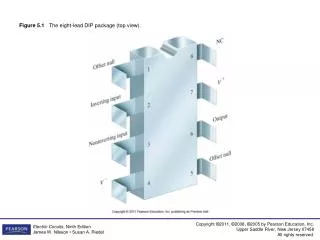
Figure 5.1 The eight-lead DIP package (top view). Figure 5.2 The circuit symbol for an operational amplifier (op amp). Figure 5.3 A simplified circuit symbol for an op amp. Figure 5.4 Terminal voltage variables. Figure 5.5 Terminal current variables. Positive.

elda
Télécharger la présentation

Figure 5.1 The eight-lead DIP package (top view).

An Image/Link below is provided (as is) to download presentation Download Policy: Content on the Website is provided to you AS IS for your information and personal use and may not be sold / licensed / shared on other websites without getting consent from its author. Content is provided to you AS IS for your information and personal use only. Download presentation by click this link. While downloading, if for some reason you are not able to download a presentation, the publisher may have deleted the file from their server. During download, if you can't get a presentation, the file might be deleted by the publisher.

E N D

Presentation Transcript


  1. Figure 5.1 The eight-lead DIP package (top view).

  2. Figure 5.2 The circuit symbol for an operational amplifier (op amp).

  3. Figure 5.3 A simplified circuit symbol for an op amp.

  4. Figure 5.4 Terminal voltage variables.

  5. Figure 5.5 Terminal current variables. Positive

  6. Figure 5.6 The voltage transfer characteristic of an op amp.

  7. Figure 5.7 The op amp symbol with the power supply terminals removed.

  8. Figure 5.8 The circuit for Example 5.1.

  9. Figure 5.9 An inverting-amplifier circuit.

  10. Figure 5.10 An inverting amplifier operating open loop.

  11. Figure 5.11 Inverting amplifier for Example 5.2.

  12. Figure 5.12 A summing amplifier.

  13. Figure 5.13 A noninverting amplifier.

  14. Figure 5.14 The noninverting amplifier design of Example 5.3.

  15. Figure 5.15 A difference amplifier.

  16. Figure 5.16 The difference amplifier designed in Example 5.4.

  17. Figure 5.17 A difference amplifier with common mode and differential mode input voltages.

  18. Figure 5.18 An equivalent circuit for an operational amplifier.

  19. Figure 5.19 An inverting-amplifier circuit.

  20. Figure 5.20 A noninverting-amplifier circuit.

  21. Figure 5.21 An op amp circuit used for measuring the change in strain gage resistance.

  22. Figure P5.1

  23. Figure P5.2

  24. Figure P5.3

  25. Figure P5.4

  26. Figure P5.5

  27. Figure P5.6

  28. Figure P5.7

  29. Figure P5.9

  30. Figure P5.10

  31. Figure P5.12

  32. Figure P5.14

  33. Figure P5.16

  34. Figure P5.17

  35. Figure P5.18

  36. Figure P5.20

  37. Figure P5.21

  38. Figure P5.22

  39. Figure P5.23

  40. Figure P5.26

  41. Figure P5.27

  42. Figure P5.28

  43. Figure P5.29

  44. Figure P5.31

  45. Figure P5.32

  46. Figure P5.33

  47. Figure P5.34

  48. Figure P5.35

  49. Figure P5.36

  50. Figure P5.37

More Related