Hy-V 0.1 Environmental Testing Overview: Vibration, Temperature, and Pressure Assessment
This document outlines the objectives and procedures for the Hy-V 0.1 environmental testing conducted by students from Virginia Tech and the University of Virginia. The primary goal is to validate the performance of five sensors and the Persistor DataLogger under flight conditions, measuring vibration, temperature, and pressure. This preliminary flight test is instrumental in preparing for the upcoming Hy-V project launch in 2010/2011, ensuring that actual measurements align with expected values. Students will gain hands-on experience in instrumentation, supporting their education in engineering.

Hy-V 0.1 Environmental Testing Overview: Vibration, Temperature, and Pressure Assessment
E N D
Presentation Transcript
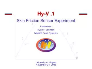
Hy-V 0.1 Environmental Testing Phillip Jasper Ryan Johnson Mitchell Foral Hy-V Virginia Tech and University of Virginia December 2008
Overview • Objective: • Test the vibration, external and internal temperature, and pressures experienced in flight • Flight qualify the five sensors and Persistor DataLogger • Students to gain experience in several areas of engineering by engaging in a student run sounding rocket experiment • Expected to prove: • Prove the equipment are viable for the Hy-V Project to be launched in 2010/2011 • Measured values match predicted values of vibration, pressure, and temperature
Importance of Hy-V 0.1 Act as a Preliminary Flight test: Students already involved in Hy-V scramjet flight experiment Hy-V is an experiment executed between UVA and VT Flight will give UVA and VT a chance to work together to achieve a successful flight prior to the flight experiment These students will be able to advise faculty and peers on the sounding rocket process Important for students to broaden their knowledge of instrumentation Given experience with instrumentation, students will be able to advise on sensor function for the future
Science and Theory • Vibration, Temperature, and Pressure profiles must be known for Hy-V Project to be successful • Certain pieces of equipment unique to this project are sensitive to these parameters http://upload.wikimedia.org/wikipedia/commons/5/55/X-43A_(Hyper_-_X)_Mach_7_computational_fluid_dynamic_(CFD).jpg
Temperature Sensor • Omega P-L Series 100 Ohm Platinum RTD • Operating Temperature: -100 C to +400C (dependent on cable covering) • 1/8” Mounted Thread • Accuracy Available up to 10 DIN (δT = +/- 0.1 X (0.3+0.005 |T|)) • Probe is 6” Long with wiring, main body is 2” http://www.omega.com/ppt/pptsc.asp?ref=P-Ultra_RTD
Pressure Transducer • Honeywell ASDX100 • Supply Voltage: 4.75V to 5.25V dc • Max Supply Voltage: 6.50V dc • Consumption Current: 6 mA • Lead Temperature: 250 C • Pressure Range: 0 – 100 PSI • Sensitivity: 0.040 V/PSI • Accuracy: +/- 2% • Operating Temperature Range: -20 C to +105 C • Vibration max: 10G at 20-2000 Hz • Shock max: 50G for 11 ms • Approximate Price: $25 http://www.datasheetarchive.com/Thumbnails/Datasheet-09/tnDSA00145182.jpg
Accelerometer • Freescale Semiconductor MMA3201 • Supply Voltage: 4.75V to 5.25V dc • Consumption Current: 6 - 10 mA • Sensitivity: 50 mV/g • Operating Temperature Range: -40 C to +125 C • Vibration max: 45g
Inertial Sensor • Analog Devices High Precision Tri-Axis Inertial Sensor ADIS16355 • Operating Temperature Range: -40 C to +85 C • Tri-axis gyroscope with digital range scaling • 14-bit resolution • +/- 10 g measurement range • Supply Voltage 4.75 – 5.25 V • 2000 g Shock Qualified • Size: 23 mm X 23 mm X 23 mm http://www.soel.ru/cms/i/?/360241$[200x0].jpg
UVA Skin Friction Sensor Skin friction sensor specifications: Operates in excess of 1000 degrees C. Between 4 and 10 mm^2 in surface area. Frequency response in the kHz range. Power in: 3-20V From the manufacturer: Analog signal output Small footprint Low weight Low power consumption
Current Board Options • Persistor DataLogger CF2 • Motorola 68332 based single board computer • ADC: 8 Channels at 12-bit, 4 channels at 16 bit • Accepts 3.6 to 20 Volt power input • Draws 5 to 50 mA current at 3.3 VCurrently • RockON! Board (fall back): • Voltage Range: 0-5V • 8 Channels • 10 Bit Resolution • 16 MB Data capacity • 50 Hz sampling rate • 30 minutes of data • PC/104+ • Currently owned by VT • Minimum boot time 5-15 secs • Experienced boot time at VT – a few minutes
Concept of Operations: • Shortly after T-zero, G-Switch Closes • Data logger boots, Sensors turn on • CF2 computer begins executing code • Logging software is interrupt-driven • Data is sampled over SPI bus • Data is written directly to Compact Flash • Compact Flash card recovered with payload
UVA Concept of Operations • Skin friction sensor • Activated by G-switch • Takes readings from inside payload bay, sends them to processor to store into memory until memory is exhausted • Instead of storing data directly, take running averages over periods of time so less memory is needed
Shared Can Logistics UVA: 25% VT: 75% • Two Skin Friction sensors • Largest sensors • Location: irrelevant • 5 Sensors • Smaller sensors • Positioning somewhat relevant • Circuit board
Shared Can Logistics-Systems (cont) • UVA will make several trips to VT • systems integration • substructure integration • DILT collaboration • UVA subsystem team will assist VT’s System team • Supply with adequate experimental component • Sensors • Code • Special needs (IE voltage requirements)
Shared Can Logistics(cont)-Mech and Aero • VT and UVA will collaborate on structure design • Solid modeling • Material Selection • Fabrication • Element analysis (determine structural integrity) • VT and UVA will divide aero analysis • Expected instrumentation reading • Expected rocket loads
Shared Can Logistics(cont)-Management • UVA and VT teams will collaborate on weekly basis next semester • Management- Weekly meetings • Systems and Mech- meet every other week • UVA and VT will work over the next month to: • Delegate specific duties • Arrange travel • More in-depth system analysis
Flow Chart Diagram for Flight Test Board Turns on Assessment of Test Sensors Power on Recovery of DATA Ignition of Rocket Tripping of G-Switch Code Execution Begins Recovery of Rocketv Deintegrate Splash Down Yes Stop Code Is memory Full? No Keep Executing Code
Subsystem Overview • Electrical and Power Supply (EPS) • EPS subsystem will provide power to all sensors. • EPS subsystem will remain between 20 and 40 Degrees Celsius at all times • Design wiring scheme • Communication and Data Handling • Handle the transfer and storing of data from sensors to the CF2 • Thermal and Environment • Track temperature profiles and requirements • Track pressure expectations and component requirements • Track vibration levels and component limitations • Systems • Track mass and power budgets • Integration of payload into the can (support from structures) • Structures • Design interior structure of the canister and provide necessary support and vibration resistance for payload
Special Mission Requirements • VT would like to measure temperature and pressure near the surface of the rocket. • This requires access to a static port near the wall of the rocket • If impossible to integrate pressure sensor near the rocket skin, the sensors will simply be placed in the RockSat canister.
Management Chris Koehler and Shawn Carroll Chris Goyne Advisor UVA VT Kevin Shinpaugh PM: Ryan Johnson PM: Kyle Knight Mech and Aero Systems Sean Flemming Mark Paretic Matt Banks Archie Raval Jess Quinlan Mitchell Foral Max Rusche Preston Cupp Phil Jasper Chris Sweeney Shaun Masavage Naeem Ahmed Jason Henn Dmitry Volodin Ben Leonard
Test Plans • Required tests include: • Structural testing • To ensure the payload will survive takeoff (i.e. vibration testing) • Environment Testing • Running full simulations for Temperature, Pressure, and Vibration levels • Day In The Life (DITL) Testing • At least two full simulations to exhibit the functionality of the payload. This will entail the payload being operated on a bench as an integrated payload for the entire mission life (less than 30 minutes) • Tests will also be done on each piece of equipment to ensure they are operative.
Conclusion • We have a plan to place multiple sensors on board • These sensors will be flight qualified for Hy-V • The information gathered will help the Hy-V team plan their components and mission profile • Information of sensors’ performance will be used on later flight experiments: • UVA shear sensor experiment • Hy-V
Appendix Temperature Sensor (RTD) - http://www.omega.com/ppt/pptsc.asp?ref=P-Ultra_RTDInvensys ASDX100 Pressure Sensor - http://www.ic-on-line.cn/iol_asdx005d44r/pdfview/2840599.htm AS Autosport Pressure Transducer - http://www.sensorsone.co.uk/products/0/36/AS-Autosport-Pressure-Transducer.html MMA3201 Accelerometer - http://www.alldatasheet.net/datasheet-pdf/pdf/188041/FREESCALE/MMA3201.html ADIS16355 Inertial Sensor - http://www.analog.com/en/other/multi-chip/adis16355/products/product.html