Orthographic Views and Isometric Representation Using First Angle Projection Method
This document provides a guide for preparing orthographic views of a simple machine component using the first angle method of projection. It includes detailed step-by-step procedures with examples of isometric views alongside the corresponding front, top, and side views. Important details such as aligning dimensions for accurate representation are emphasized. The figures illustrate the projection of different views and the angles to be used during the drawing process. This educational material is essential for students and professionals in the field of engineering drawing and design.

Orthographic Views and Isometric Representation Using First Angle Projection Method
E N D
Presentation Transcript
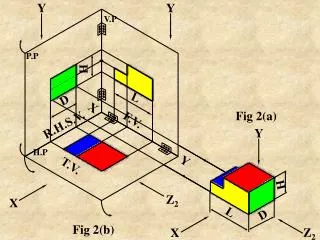
Y Y V.P P.P H X L D Fig 2(a) Y F.V. R.H.S.V. Y H.P T.V. H Z2 X L D Z2 X Fig 2(b)
Note : Ist angle means, the block is assumed in front of V.P, above H.P and inside P.P, as in fig. 2(b) where the F.V. is projected on V.P, seen in X direction, T.V. is projected on H.P, seen in Y direction & R.H.S.V. is projected on P.P, seen in Z2 direction
Fig. 2(c) shows turning of the planes H.P & P.P with their respective hinges, considering plane V.P as fixed plane. • It may be noted that :- • F.V. (X directional view) is on V.P, T.V. (Y directional view) is on H.P, while R.H.S.V (Z2 directional view) is on P.P • b) F.V is within L & H, T.V is within L & D, While R.H.S.V is within H & D. • c) The symbol for Istangle method of projections is placed as shown on fig. 2(c)
P.P V.P H D R.H.S.V. F.V. H.P L Y X T.V. Fig. 2(c)
Step by step procedure Suggested to prepare Orthographic views (First angle method) for The simple component Shown pictorially in figure
20 20 40 20 60 80 Ø40 R40 100 20 ISOMETRIC VIEW X
20 20 R20 80 20 20 ø40 80 R40 100 R.H.S.V FRONT VIEW SYMBOLIS NOT MARKED SCALE: 1:1 TOP VIEW
FIGURE SHOWS ISOMETRIC VIEW OF A SIMPLE OBJECT(WITHOUT DIMENSIONS) SHOW ITS THREE ORTHOGRAPHIC VIEWS a • Front View • Top View • L.H.S.View b B 2 3 A Use First Angle Method c 1
b B 2 3 A 1 F.V L.H.S.V. a b c 3 T.V
FIGURE SHOWS ISOMETRIC VIEW OF AN OBJECT(WITHOUT DIMENSIONS) SHOW ITS THREE ORTHO GRAPHIC VIEWS a • Front View • Top View • L.H.S.View • Front View • Top View • L.H.S.View c 3 b A Use Third Angle Method 2 1
c a b TOP VIEW 3 A 2 1 FRONT VIEW L.H.S VIEW
Aim : Figure shows isometric view, of a simple machine component. Draw its following Orthographic views, & dimension them. • Front View • Top View • R.H.S. View Use First Angle Method of projection
L = 75+25=100 X H = 10+30=40 R25 D=50 20 30 10 10 40 10 75 Figure 50 Figure, is the isometric view
L=100 F.V H=40 L=100 T.V D=50 D=50 S.V H=40 10 40 10 R.H.S.V. F.V. 20 50 R25 10 40 25 75 ORTHOGRAPHIC VIEWS T.V.
40 SQ Ø30,Depth 10 25 SQ 10 30 15 SQ 35 5 10 35 5 40 ISOMETRIC ORTHO. VIEWS 45 15
10 30 5 10 35 45 35 15 40 Sq 25 Sq 40 10 5 15 Sq Ø30 F.V. R.H.S.V. T.V.
Exercise :- • Figure shows the isometric view of a vertical shaft support. • Draw its all the three views, using first angle method of projections. • Give the necessary dimensions as per aligned system.
Ø64 Ø40 24 50 25 10 140 20 48 ISOMETRIC VIEW
Ø40 Ø64 24 50 30 10 140 14 48 14 70 L.H.S.V FRONT VIEW TOP VIEW
Exercise :- Isometric view of a rod support is given. Draw its all the three orthographic views, using first angle method of projections. Give all the dimensions.
R22 40 Ø24 20 80 60 20 30 16 20 140 20 X 40 ISOMETRIC VIEW
R22 30 30 30 66 26 10 20 40 20 80 140 FRONT VIEW RIGHT SIDE VIEW SCALE: 1:1 TOP VIEW
20 R20 30 16 30 8 10 20 10 25 100 R8 45 ISOMETRIC ORTHO. VIEWS
R20 20 30 10 100 16 8 30 25 20 45 R8