
Analog to Digital Conversion
E N D
Presentation Transcript
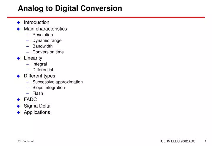
Analog to Digital Conversion • Introduction • Main characteristics • Resolution • Dynamic range • Bandwidth • Conversion time • Linearity • Integral • Differential • Different types • Successive approximation • Slope integration • Flash • FADC • Sigma Delta • Applications CERN ELEC 2002 ADC
Analog to Digital Converter • Analog input - Digital output • Most of the time commercial ASICs • Converts voltage or current • What is to be converted? • Voltage, Current, Charge, Time • Analog input processing is necessary • To convert the measured quantity in a tension • To adapt the impedances • To filter • To adapt the amplitude • What is the expected resolution? • What is the dynamic range? • What is the expected linearity? • How often is a conversion needed? CERN ELEC 2002 ADC
Resolution • An ADC is given as an n-bit ADC • The least significant bit gives the resolution of the ADC • Related to full scale if the ADC is linear • LSB = A/2n • Linear 8-bit ADC with a 1V full scale input • Resolution = 1/28 = 3.9 mV (0.39%) CERN ELEC 2002 ADC
Dynamic range • Ratio between the minimum and the maximum amplitude to be measured • e.g. calorimeter signal 10 MeV to 2 TeV gives a 2 106 dynamic range • In case of linear system the dynamic range is related to the number of bits (and hence the resolution) • an 8-bit ADC has a 256 dynamic range • In case of large dynamic range (as for a calorimeter) some non-linearity has to be introduced • linear ADC for the previous example would require 21 bits! • Often used terms in physics: • n-bit resolution • n-bit dynamic range • example: • 8-bit resolution for a 12-bit dynamic range means that a signal in the range 1-4000 is measured with a resolution of 0.39% CERN ELEC 2002 ADC
Conversion time and Bandwidth • How often can a conversion be done • a few ns to a few ms depending on the technology • 100 MHz FADC to slow sigma-delta • Input bandwidth • Maximum input signal bandwidth • Track and hold input circuitry • Conversion frequency (FADC) CERN ELEC 2002 ADC
ADC transfer curve • Ideal ADC • Errors • Offset • Integral non-linearity • Differential non-linearity CERN ELEC 2002 ADC
Non Linearity Integral linearity • Non linearity: maximum difference between the best linear fit and the ideal curve CERN ELEC 2002 ADC
Differential non-linearity • Least Significant Bit (LSB) value should be constant but it is not • The difference with the ideal value shall not exceed 0.5 LSB • Easy way of seeing the effect • random input covering the full range • frequency histogram should be flat • differential non-linearity introduces structures CERN ELEC 2002 ADC
Types of ADC • Successive approximation • Single slope integration • Dual slope integration • Flash ADC • Sigma-Delta CERN ELEC 2002 ADC
Successive approximation • Compare the signal with an n-bit DAC output • Change the code until • DAC output = ADC input • An n-bit conversion requires n steps • Requires a Start and an End signals • Typical conversion time • 1 to 50 ms • Typical resolution • 8 to 12 bits • Cost • 15 to 600 CHF CERN ELEC 2002 ADC
Vin - + Counting time StartConversion StartConversion Enable S Q R N-bit Output Counter C Clk Oscillator IN Single slope integration • Start to charge a capacitor at constant current • Count clock ticks during this time • Stop when the capacitor voltage reaches the input • Cannot reach high resolution • capacitor • comparator CERN ELEC 2002 ADC
Charge with a currentproportional to the input Counting time Dual slope integration (Wilkinson) • Capacitor charged with a current proportional to the input during a fixed time • Discharge at constant current • Count of clock ticks during the discharge CERN ELEC 2002 ADC
Dual slope integration (2) • Advantages • Capacitor value is not important although has to be of good quality • Comparator error can be canceled by beginning and ending each conversion cycle at the same voltage • Clock frequency errors can be cancelled by using the same clock to define the charge time • Typical resolution • 10 to 18 bit • Conversion time • Depends on the clock frequency CERN ELEC 2002 ADC
Flash ADC • Direct measurement with 2n-1 comparators • Typical performance: • 4 to 10-12 bits • 15 to 300 MHz • High power • Half-Flash ADC • 2-step technique • 1st flash conversion with 1/2 the precision • Subtracted with a DAC • New flash conversion • Waveform digitizing applications CERN ELEC 2002 ADC
X 4 - S&H 3-bit FADC 3-bit DAC 3-bit S&H Stage 1 Stage 2 Stage 3 Stage 4 4-bit FADC Input 3-bit 3-bit 3-bit 3-bit 4-bit Time Adjustment & Digital Error Correction 12-bit Flash ADC (cont) • Pipeline ADC • Input-to-output delay = n clocks for n stages • One output every clock cycle • Saves power (less comparators) CERN ELEC 2002 ADC
q e(x) Effective number of bits • An n bit ADC introduces a quantization error • Effective number of bits of an n-bit FADC • n’ giving the correct SNR • Example: AD9235 12-bit 20 to 65 MHz • SNR = 70 dB • Effective number of bits = 11.4 • Encoding a signal (A/2) sinwt with A being the full scale will give an error • Signal to Noise Ratio CERN ELEC 2002 ADC
Shannon Theorem • A signal x(t) has a spectral representation |X(f)|; X(f) = Fourier transform of x(t) • A signal x(t) after having been digitised at the frequency fs, has a spectral representation equal to the spectral representation of x(t) shifted every fs • If X(f) is not equal to zero when f > fs/2, there is spectrum overlapping • The Shannon theorem says that x(t) can be reconstructed after digitisation if the digitising frequency is at least twice the maximum frequency in x(t) spectral representation • This is mathematical only, as it supposes perfect filtering CERN ELEC 2002 ADC
Example (1) • “Typical” physics pulse • 100 ns rising and falling edge • Effect of a digitisation at 10 MHz and 20 MHz CERN ELEC 2002 ADC
Example (2) • 100 ns square pulse • Digitisation at 10 MHz and 20 MHz CERN ELEC 2002 ADC
1/2*T0 +T0 -T0 Using FADC • Do not forget to make a frequency analysis of the signal • Any spectrum overlapping introduces noise • Take into account the effective number of bits • Filtering is necessary • Before digitisation (analog) to cut the input signal frequency spectrum • After digitisation (digital) to extract the signal frequency spectrum and to compensate the effect of digitisation over a finite time window CERN ELEC 2002 ADC
|e(f)| q f e(x) -fs/2 +fs/2 Over-sampling ADC • If fs is higher than the frequency f0 of the signal to be measured then after filtering the error will become • Assuming the error is a white noise, its power spectral density is flat within the range [–fs/2,fs/2] CERN ELEC 2002 ADC
Over-sampling ADC (cont) • The signal to noise ratio when encoding a signal (A/2) sinwt, with A being the full scale, will be • Hence it is possible to increase the resolution by increasing the sampling frequency and filtering • Example : an 8-bit ADC becomes a 9-bit ADC with an over-sampling factor of 4 • But the 8-bit ADC must meet the linearity requirement of a 9-bit CERN ELEC 2002 ADC
- Input Output 1-bit ADC 1-bit DAC 1rst Order Sigma-Delta Modulator Sigma-Delta ADC • The output of this modulator is a digital stream • Average = Input • Over-sampling ratio M=fs/f0 CERN ELEC 2002 ADC
Sigma-Delta ADC (cont) • The signal to noise ratio when encoding a signal (A/2) sinwt, with A being the full scale, will be • Gain of 1.5 bits per octave increase of M • M = 2350 to have a 16-bit ADC • Higher orders sigma-delta are implemented • Examples (Analog Devices) • 16-bit, 2.5 MHz • 24-bit, 1kHz The design of low-voltage, low-power sigma-delta modulators Shahriar Rabii & Bruce Wooley Kluwer academic publisher CERN ELEC 2002 ADC
Resolution/Throughput Rate CERN ELEC 2002 ADC
Power • Power is going down • Examples • 8-bit, 200MSPS: 1.3 mW/MSPS • 10-bit, 10 MSPS core used in ALICE TPC read-out: <20 mW • 24-bit, 1 kSPS: 45 mW CERN ELEC 2002 ADC
Applications • In HEP we are facing large number of channels • The quantity to be measured depends on the type of detector • Charge in the case of a lead glass calorimeter with PM read-out • Voltage in the case of a lead glass calorimeter with triode and preamplifier shaper read-out • Low cost Charge integrating ADC for a LEP calorimeter • High speed peak sensing ADC for a neutrino experiment • Non linear ADC for an LHC experiment • FADC with numerical filtering for an LHC trigger application CERN ELEC 2002 ADC
Charge integrating ADC (1) • High resolution: 12-bit • High dynamic range: 15-bit • High density: 96 channel per Fastbus board • Low speed: 1 ms conversion time • Low cost per channel • Principle: • Single ADC for 48 channels • Charge input integration and storage CERN ELEC 2002 ADC
Charge integrating ADC (2) • Block diagram CERN ELEC 2002 ADC
Charge integrating ADC (3) • Performance • 12-bit resolution, 15-bit dynamic range • Conversion time tcvt = 48 (tc + ts) = 960 µs • where tc = ADC conversion time = 12 µs • and ts = settling time for multiplexer and amplifiers = 8 µs. CERN ELEC 2002 ADC
Peak sensing ADC (1) • 12-bit resolution • Low dead-time : 8 ms • Data buffering CERN ELEC 2002 ADC
+ + - - C Peak sensing ADC (2) • Block diagram Vin FIFO ADC Read-out 12-bit Gate CERN ELEC 2002 ADC
ADC for an LHC experiment (1) • ATLAS Liquid Argon calorimeter • High dynamic range: 16-bit • Shaping of the signal to minimise pile-up • Sampling every 25 ns (bunch crossing period) • Level-1 pipeline Shaping CERN ELEC 2002 ADC
ADC for an LHC experiment (2) • Block diagram CERN ELEC 2002 ADC
ADC for an LHC experiment (3) • Performance • Pedestal stability to 0.1 ADC counts • Noise equivalent to 20 MeV • Integral non-linearity below 0.25% • Conversion time : 25 ns per sample CERN ELEC 2002 ADC
FADC for LHC trigger purpose (1) • Analog summation on the detector to form the trigger tower • Shaping time covers several bunch crossings • FADC and numerical filtering to: • Extract the energy • Extract the bunch crossing responsible for it CERN ELEC 2002 ADC
FADC for LHC trigger purpose (2) • Block diagram CERN ELEC 2002 ADC
FADC for LHC trigger purpose (3) • Filter algorithm : Finite Impulse Response CERN ELEC 2002 ADC