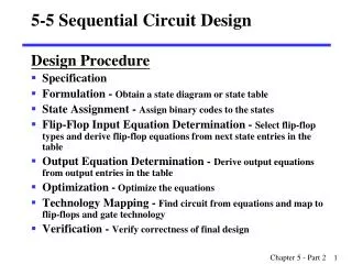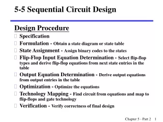
Sequential circuit design with metastability
Sequential circuit design with metastability. Lecture 11 October 3, 2017 Preliminary version. Sequential Logic. Combinational logic output depends on current inputs. clk. clk. Sequential logic output depends on current and previous inputs

Sequential circuit design with metastability
E N D
Presentation Transcript
Sequential circuitdesignwithmetastability Lecture11 October 3, 2017 Preliminary version
Sequential Logic • Combinational logic • output depends on current inputs clk clk • Sequential logic • output depends on current and previous inputs • Requires separating previous, current, future • Called state or tokens • Examples: Finite state machine (FSM), pipeline Combinatorial logic Combinatorial logic in out in out Figure 1.67 from W&H MCC092 Integrated Circuit Design - sequential circuit design
Sequencing • If tokens move through pipeline at constant speed, no sequencing elements are necessary • Ex: fiber-optic cable • Light pulses (tokens) are sent down cable • Next pulse sent before first reaches end of cable • No need for hardware to separate pulses • But dispersion sets min time between pulses • This is called wave pipeliningin circuits • In most circuits, dispersion is high • Solution: delay fast tokens so they don’t catch up on slow ones. MCC092 Integrated Circuit Design - sequential circuit design
Sequencingoverhead • Solution: Use flip-flops to delay fast tokens so they move through exactly one stage each cycle. • Drawback: Adds some delay also to the slow tokens • Thus, circuit is slower than just logic propagation delay • Added delay is called sequencing overhead • Some people call this clocking overhead • But it applies to asynchronous circuits too • Inevitable side effect of maintaining sequence MCC092 Integrated Circuit Design - sequential circuit design
This lecture • Compute sequencing overhead with flip-flops • Compute maximum clock frequency • Also with clock skew • Understand causes of delays in flip-flops and abit about their design tradeoffs • But not design them • Synchronization of asynchronous signals • Metastability MCC092 Integrated Circuit Design - sequential circuit design
Return to adder example Figure 1.67 from W&H MCC092 Integrated Circuit Design - sequential circuit design
Ripple-carry adder (from postlab 2) A way of drawing the same thing with less detail for thecombinational logic (CL) MCC092 Integrated Circuit Design - sequential circuit design
Sequencing with flip-flops Fllip-flop: Edge-triggered (positive edge) holds data until next edge • Goals today: • Given a certain CL determine the minimum possible Tcwith and without clock skew. • Given certain fc, clock skew and flip-flops determine timing requirements on CL. Part of Figure 10.2 from W&H MCC092 Integrated Circuit Design - sequential circuit design
Characterizing combinational logic • Propagation delay, tpd: • Maximum time until output finally reaches VDD/2. • Output is guaranteed not to change aftertpd. • Contamination delay, tcd: • Minimum time until output initially reaches VDD/2. • Output is guaranteed not to change beforetcd. Figure 10.4 (a) from W&H MCC092 Integrated Circuit Design - sequential circuit design
Flip-flop operation and delays Edge-triggered (positive edge) holds data until next positive clock edge. Input is called D output is called Q. Input D has to be ready before clock edge happens, so that correct data is read. Input D has to be stable long enough after clock edge happened to be correctly locked by flip-flop. From clock edge happening it takes some time until output Q is available, there is a maximum and a minimum delay. Figure 10.4 (b) from W&H MCC092 Integrated Circuit Design - sequential circuit design
Flip-flop operation and delays sampling window, aperture Setup time is always positive. Hold time can be positive, zero or negative. Figure 10.4 (b) from W&H MCC092 Integrated Circuit Design - sequential circuit design
What is minimum Tc? tpd, tcd Make sure result from CL is always there when next clock edge happens: Otherwise there is a setup violation. MCC092 Integrated Circuit Design - sequential circuit design
Maximum propagationdelay Figure 10.5 from W&H MCC092 Integrated Circuit Design - sequential circuit design
What is minimum Tcwith clock skew? tpd, tcd Clock skew = difference in delay (arrival time) for clock signals. We do not know which way the difference will go. Make sure result from CL is always there anyways when next clock edge happens Figure 10.15 (a) from W&H MCC092 Integrated Circuit Design - sequential circuit design
Maximum propagationdelaywithclockskew • Decreases maximum propagation delay MCC092 Integrated Circuit Design - sequential circuit design
Another potential problem tpd, tcd What if result from CL changes before the previous result has been read? Then tokens are merged and data is lost. MCC092 Integrated Circuit Design - sequential circuit design
Minimum contaminationcelay Figure 10.9 from W&H MCC092 Integrated Circuit Design - sequential circuit design
Hold violation with clock skew? tpd, tcd What if result from CL changes before the previous result has been read and we have clock skew? Then tokens are merged and data is lost. MCC092 Integrated Circuit Design - sequential circuit design
Minimum contaminationdelaywithclockskew • Increases minimum contamination delay Figure 10.15 (b) from W&H MCC092 Integrated Circuit Design - sequential circuit design
Is setup or hold violations worse? MCC092 Integrated Circuit Design - sequential circuit design
System balancing • A well-designed system is balanced • No need to overdesign one part if another part limits system performance. • Tradeoff between: • CL: delays, area, power • Flip-flop design: delays, area, power, metastability • Clock generation and distribution: delay clock skew, area, power MCC092 Integrated Circuit Design - sequential circuit design
How design a flip-flop? • Important requirements: • Data is always maintained and restored • Short delays • Low capacitive load on clocks signals • Small • Enable • Reset/set (synchronous or asynchronous) • Scan chain MCC092 Integrated Circuit Design - sequential circuit design
D-Latch Example A MUX on the input allows us to either load new data or keep old data Two C-switches make a simple MUX MCC092 Integrated Circuit Design - sequential circuit design
Using tri-state inverters _ f However, an inverter and a C-switch can be replaced by tri-state inverter f _ f f MCC092 Integrated Circuit Design - sequential circuit design
D-Latch Design • Tristate feedback + Static • Backdriving risk • Static latches are essential so that data does not disappear because of leakage X f _Q D _ f f _ f MCC092 Integrated Circuit Design - sequential circuit design
D-Latch Design • Buffered input + Fixes diffusion input + Makes latch noninverting f X Q D _ f f _ f MCC092 Integrated Circuit Design - sequential circuit design
D-Latch Design Q • Buffered output + No backdriving • Widely used in standard cells + Very robust (most important) • Rather large • Rather slow (1.5 – 2 FO4 delays) • High clock loading f X Q D _ f f _ • f MCC092 Integrated Circuit Design - sequential circuit design
D-type Flip-Flop Design • Flip-flop is built as pair of back-to-back latches _Q f f X X D Q _ f _ f f f _ f _ f MCC092 Integrated Circuit Design - sequential circuit design
D-type Flip-Flop Design • Data is transferred from master to slave when CLK=1 Q´ data Q f=1 Q´ data Q f=0 _ f _ f f f • New data is received by master when CLK=0, while slave stores previous data MCC092 Integrated Circuit Design - sequential circuit design
HS65_LS_DFPRQ MCC092 Integrated Circuit Design - sequential circuit design
Clock generation Master latch with NOR2 Slave latch with tristate NAND MCC092 Integrated Circuit Design - sequential circuit design
Master latch 2.6 um × 2.8 um RN CPI CPN CPN DATA CP CPI TO SLAVE CPI RN INV Tristate Tristate 2NOR MCC092 Integrated Circuit Design - sequential circuit design
Slave latch 2.6um × 3.2um RN Q CPN CPI FROM MASTER INV INV INV+TG INV Tristate NAND MCC092 Integrated Circuit Design - sequential circuit design
DFF layout in cell library 4.0 um 2.6 um MCC092 Integrated Circuit Design - sequential circuit design
Summary • Wetook a step from combinatoriallogictosequentiallogic: • CL delays • FF delays • Setup and holdviolations: • Constraints on CL delays from fc, flip-flop delays and clockskew • System tradeoffs – don’toverdesignany part! • Edge-triggered flip-flop from two back-to-back latches: one master, one slave • Enable • Set/Reset • Scan chains • Had a look at a D-type FF in STMicroelectronics cell library • Compared to a master/slave design using our design template. • Results: 6.0 μmwide compared with ST 4.0 μm • Nextup: synchronization and metastability MCC092 Integrated Circuit Design - sequential circuit design