Download
1 / 17
170 likes | 346 Vues
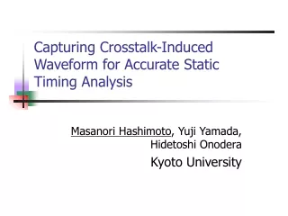
Capturing Crosstalk-Induced Waveform for Accurate Static Timing Analysis. Masanori Hashimoto , Yuji Yamada, Hidetoshi Onodera Kyoto University. Never provide accurate waveforms. How cope with crosstalk-induced waveform?. Problems of Conventional Methods.

E N D
Capturing Crosstalk-Induced Waveform for Accurate Static Timing Analysis Masanori Hashimoto, Yuji Yamada,Hidetoshi Onodera Kyoto University
Never provide accurate waveforms How cope with crosstalk-induced waveform?
Problems of Conventional Methods • Conventionally crossing-point approach • Calculate crossing timing of reference voltage e.g. 50% delay, 20-70% transition time, etc. almost the same waveforms Estimate large delay difference in error
Gate Waveform Calculation • Table look-up model • Huge characterization cost • Difficult to increase #parameter of waveform Characterization has to assume a typical waveform.
Related Works • Sasaki, ASIC/SoC Conf., 1999 • Estimate delay change vs transition timing at receiver output by circuit simulation • Simulation is necessary for every instance • Sirichotiyakul, DAC, 2001 • Estimate delay change at receiver output by look-up tables • Library extension and characterization increase
Proposed Equivalent Waveform Approach • Propose equivalent waveform propagation that makes output waveforms equal • Adjust both arrival time and slew Characterization uses typical waveforms.
Derivation of Equivalent Waveform • Fitting waveforms using least square method • Approximate entire outline Work well?NO!!
Problem of LSM • Uniform fitting weight even for unnecessary region misleads equivalent waveform. Transition finishes before noise injection. Adaptive fitting for critical region is necessary.
Proposed Method • Improved LSM with weight coefficient • To consider output behavior High gain sensitive to input Critical Region Higher weight slope Vout vs Vin curve Noiseless waveforms
Strength of Proposed Method • No library extension • No additional characterization • No additional calculation except fitting • Implemented easily with conventional STA tools
Experimental Conditions • True delay change is evaluated at Gate3 output. • Conventional Method: delay change is evaluated at Gate2 input • 100nm process, semi-global wire, 1mm coupled
Experimental Result(Crosstalk) • Agg., vic. drivers 4x, 4x, load(C1,C2)=100fF Accurate delay variation curve is obtained.
Equivalent and Actual Waveforms Cross 0.5Vdd Conventional method shifts waveform in error. Proposed method is not misled by meaningless noise.
Agg.=vic. =8x, C1=C2=100fF Agg.=vic. =8x, C1=C2=10fF Proposed method estimates more accurate curves than conventional methods. Worst case in our experiments. Agg.=vic. =4x, C1=C2=10fF
Experimental Result (Crosstalk, two aggressors) Proposed method works even when multiple aggressors.
Computational Cost • Numerical integration is necessary. • #segments: accuracy vs CPU time • CPU time increase is evaluated. • Path delay calculation of inverter chain • File I/O and RC reduction are excluded. • 3-20 #segments is accurate enough. conventional method: 1.00
Conclusion • Propose equivalent waveform propagation scheme • Cope with non-monotonic waveforms • Familiar with conventional STA tools • Experimentally verify our method improves much accuracy just with 30% CPU time increase.