SlideServe
Menu
Préférences
© SlideServe · v2026

Chapter 4 -- Modular Combinational Logic

kanan avatar
32 diapositives · 584 Views · Aug 14, 2014

Chapter 4 -- Modular Combinational Logic. Decoders. Decoder Realization. More complex decoders. Example 4.1 -- Realize f(Q,X,P) =  m (0,1,4,6,7) =  M (2,3,5). Example 4.1 (concluded). SN 74138 Decoder Module. Four-to-one multiplexer design.
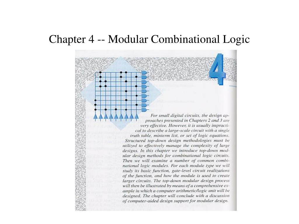
Chapter 4 -- Modular Combinational Logic - slide 1
01 / 32Chapter 4 -- Modular Combinational Logic
1 / 17

Télécharger la présentation

Chapter 4 -- Modular Combinational Logic
Une image / un lien ci-dessous est fourni (tel quel) pour télécharger la présentation

Politique de téléchargement : le contenu du site vous est fourni TEL QUEL pour votre information et votre usage personnel ; il ne peut être vendu, concédé sous licence ni partagé sur d’autres sites sans l’accord de son auteur.Le contenu vous est fourni TEL QUEL, pour votre information et votre usage personnel uniquement. Téléchargez la présentation en cliquant sur ce lien. Lors du téléchargement, si vous ne parvenez pas à télécharger une présentation, l’éditeur a peut-être supprimé le fichier de son serveur.Pendant le téléchargement, si vous ne parvenez pas à obtenir une présentation, le fichier a peut-être été supprimé par l’éditeur.

F I N

Plus de contenu associé

Transcription de la présentation
  1. Chapter 4 -- Modular Combinational Logic

  2. Decoders

  3. Decoder Realization

  4. More complex decoders

  5. Example 4.1 -- Realize f(Q,X,P) = m(0,1,4,6,7) = M(2,3,5)

  6. Example 4.1 (concluded)

  7. SN 74138 Decoder Module

  8. Four-to-one multiplexer design

  9. Use a 74151A multiplexer to Realizef(x1,x2,x3) = m(0,2,3,5) Figure 4.30

  10. Half Adders Figure 4.35 (a) -- (c)

  11. Full Adders Figure 4.35 (d) -- (g)

  12. Ripple Carry Adder Figure 4.36

  13. Addition Time for a Basic Ripple-Carry Adder Let tgate = the propogation delay through a typical logic gate Half adder propagation delays tadd = 3 tgate tcarry = 2 tgate Full adder propagation delays tadd = 3 tgate tcarry = 2 tgate Ripple-Carry Adder (n-bits) tadd = (n - 1)2 tgate + 3 tgate = (2n + 1) tgate

  14. SN7482 Two-Bit Pseudo Parallel Adder Module Package Pin Configuration

  15. SN7482 Pseudo Parallel Adder -- Truth Table

  16. SN7482 Pseudo Parallel Adder -- Logic Diagram

  17. SN7482 Two-Bit Adder -- Logic Equations C1 = C0A1 + C0B1 + A1B1 (4.20) 1 = C0C1 + A1C1 + B1C1 + A1B1C0 = C1(C0 + A1 + B1) + A1B1C0 = (C0+A1)(C0+B1)(A1+B1) (C0 +A1+B1) +A1B1C0 = (C0+ A1B1)(A1+B1)(C0 +A1+B1) +A1B1C0 (4.21) = [C0(A1+B1)+ C0A1B1](A1+B1)+A1B1C0 = C0A1B1+C0A1B1+C0A1B1+A1B1C0 = C0  A1  B1 Similarly C2 = C1A2 + C1B2 + A2B2 (4.22) 2 = C1  A2  B2

  18. Add Time for SN7482 Adder Circuits SN7482 propagation delays t1 = 5 tgate tC1 = 2 tgate t2 = 6 tgate tC2 = 4 tgate SN7482-based ripple-carry adder (n-bits) tadd = (2n + 2)tgate

  19. SN7483 Four-Bit Adder Module Package Pin Configuration

  20. SN7483 Four-Bit Adder Module -- Logic Diagram

  21. SN7483 Four-Bit Adder -- Logic Equations Pi = (BiAi)(Ai + Bi) = (Ai + Bi)(Ai + Bi) = Ai  Bi (4.24) i = Pi  Ci-1 = Ai  Bi  Ci-1 (4.25) C1 = [C0(A1B1) + (A1 + B1)] = [C0(A1B1)](A1 + B1) = (C0+(A1B1))(A1 + B1) = C0A1 + C0B1 + A1B1 (4.26) Similarly Ci = Ci-1Ai + Ci-1Bi + AiBi

  22. Add Times for SN7483 Adder Circuits SN7483 propagation delays t1 = 3 tgate t2 = t3 = t4 = 4 tgate tC1 = tC2 = tC3 = tC4 = 3 tgate SN7483-based Ripple-Carry Adder (n-bits) tadd = (3m + 1)tgate where m = n/4.

  23. Fully Parallel Three-Bit Adder c0 = x0y0(4.30) s0 = x0 y0 c1 = x1y1c0’+x1y1c0+x1y1’c0+x1’y1c0 = x1y1+(x1y1)c0 = x1y1+(x1y1)(x0y0) (4.31) s1 = x1y1c0 = x1y1 x0y0 c2 = x2y2+(x2y2)c1 = x2y2+(x2y2)[x1y1+(x1y1)(x0y0)] = x2y2+(x2y2)(x1y1)+(x2y2)(x1y1)(x0y0) (4.32) s2 = x2y2c1 = x2y2[x1y1+(x1y1)(x0y0)]

  24. Add Time for a Fully Parallel Adder Assuming a three-level realization tadd = 3tgate However, the fan in requirements become impractical as n increases.

  25. Carry Look-Ahead Adders -- Basic Idea Recall that ci = xiyi + xici-1 + yici-1 = xiyi + xiyici-1 + xiyici-1 + xiyici-1 + xi yici-1 = xiyi + xiyici-1 + xi yici-1 = xiyi + (xiyi + xi yi)ci-1 = xiyi + (xiyi)ci-1 Let gi = xiyi [carry generate] (4.33) pi = xiyi [carry propagate] (4.34) Then ci = gi + pi ci-1 si = pi  ci-1 (4.38)

  26. Carry Look-Ahead Adders -- Three-Bit Example c0 = g0 (4.35) s0 = p0 c1 = g1 + p1c0 = g1 + p1g0 (4.36) s1 = p1 c0 c2 = g2 + p2c1 = g2 + p2(g1 + p1g0) = g2 + p2g1 + p2p1g0 (4.37) s2 = p2 c1

  27. Carry Look-Ahead Adder Design (c) Figure 4.39

  28. Add Times for Carry Look-Ahead Adders Adder modules tg = tp = ts = tgate CLA module tc = 2 tgate Overall tadd = tgate + 2 tgate + tgate = 4 tgate

  29. Binary Subtraction Circuits Recall that (R)2 = (P)2 - (Q)2 = (P)2 + (-Q)2 = (P)2 + [Q]2 = (P)2 + (Q)2 + 1 For an SN7483 adder ()2 = (A)2 + (B)2 + (C0)2 (4.39) where  = 4321, A = A4A3A2A1, and B = B4B3B2B1 If C0 = 0, A = P, and B = Q, then ()2 = (P)2 + (Q)2 . If C0 = 1, A = P, and B = Q, then ()2 = (P)2 - (Q)2 .

  30. Two’s Complement Adder/Subtracter Figure 4.41

  31. Arithmetic Overflow Detection an-1bn-1cn-2cn-1sn-1V 0 0 0 0 0 0 0 0 1 0 1 1 0 1 0 0 1 0 0 1 1 1 0 0 1 0 0 0 1 0 1 0 1 1 0 0 1 1 0 1 0 1 1 1 1 1 1 0

  32. Overflow Detection Circuits Figure 4.42