
Multiplexer
E N D
Presentation Transcript
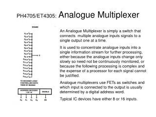
A multiplexer (MUX) is a device which selects one of many inputs to a single output. The selection is done by using an input address. Hence, a MUX can take many data bits and put them, one at a time, on a single output data line in a particular sequence. This is an example of transforming parallel data to serial data. A demultiplexer (DEMUX) performs the inverse operation, taking one input and sending it to one of many possible outputs. Again the output line is selected using an address.
A MUX-DEMUX pair can be used to convert data to serial form for transmission, thus reducing the number of required transmission lines. The address bits are shared by the MUX and DEMUX at each end. If n data bits are to be transmitted, then after multiplexing, the number of separate lines required is log2 n + 1, compared to n without the conversion to serial. Hence for large n the saving can be substantial.
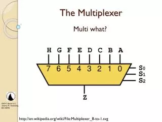
A multiplexer is a circuit with 2n data inputs, onedata output and n control inputs that select oneof the outputs. • The selected data input is selected “gated”(routed) to the output. • The n inputs encode an n-bit number thatspecifies which input is selected as the output.
Multiplexers consist of two functionally separate components, a decoder and some switches or gates. The decoder interprets the input address to select a single data bit. We use the example of a 4-bit MUX in the following section to illustrate how this works.
A 4-bit MUX Design We wish to design a 4-bit multiplexer. The block diagram is given in Fig. 9. There are 4 input data bits D0{D3, 2 input address bits A0 and A1, one serial output data bit Q, and an (optional) enable bit E which is used for expansion (discussed later). First we will design the decoder.