Conventional Facilities
Conventional Facilities. Steve Dierker Director, NSLS-II Conventional Facilities Division NSLS-II User Workshop July 17, 2007. Outline. Conventional Facilities Scope Site Plan Building Program Sustainable Design BNL Support CF Schedule & Risk Analysis

Conventional Facilities
E N D
Presentation Transcript
Conventional Facilities Steve Dierker Director, NSLS-II Conventional Facilities Division NSLS-II User Workshop July 17, 2007
Outline • Conventional Facilities Scope • Site Plan • Building Program • Sustainable Design • BNL Support • CF Schedule & Risk Analysis • Conventional Facilities Deliverables for Users • Beamline Support Space – LOB’s • Experimental Floor • Utility Services for Beamlines • Stability Goals • CF Path Forward
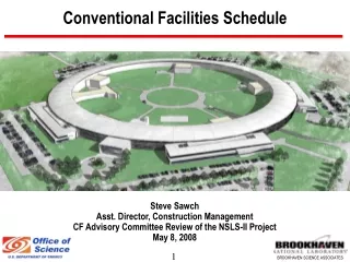
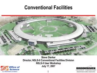
NSLS-II Siteplan Bldg 603 Substation NSLS JPSI LOB (1 of 3) NSLS-II CFN BLOC Service Bldgs (1 of 5) CHW Plant Future LOB’s Access Tunnel
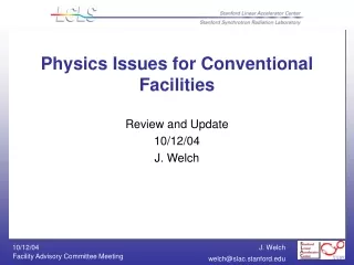
View of NSLS-II LINAC/Booster Entry Lobby LOB JPSI
NSLS-II Main Entry Lobby LINAC/Booster Entry Lobby LOB JPSI
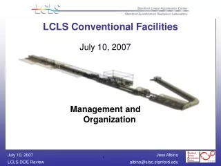
NSLS-II Floor Plan • NSLS-II Floor Plan • BLOC – Booster/LINAC/ Operations Center • LOB – Lab Office Buildings (3 base scope up to 5 future) • Service Buildings (5) • RF Area • Tunnel Area • Electrical Mezzanine • Experimental Floor • Access Corridor 2 3 3 1 2 2 4 3 3 3 2 2
Facility Program Base plan provides 3 large LOB’s to support rapid build-out of beamlines with plan for 2 more LOB’s to be added in future
Sustainable Design • DOE will require Certification to USGBC LEED “Gold” std. • Reviewing DOE guidance on how it will be applied to NSLS-II process systems • Additional investment in these areas should achieve Gold • Additional storm & potable water credits • Additional reuse/sustainable material credits • Systems for added energy efficiency • Photovoltaics & renewable energy credits • Heat recovery Y M N
BNL Support • BNL Support to the project is important and demonstrable • Warehouse Demolition & Replacement • Must remove Bldgs 86, 100, 210, 211, and 481 before FY 09 • Warehouse facility replacement is underway as GPP project • Demolition planned for Spring FY08 • Chilled Water Plant Expansion • NSLS-II and Lab will share expansion cost as both need added capacity • A/E selected and ready to begin design • Design to run concurrent with NSLS-II T-I and T-II • Construction start in FY09 and complete early FY11
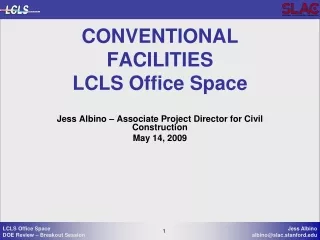
Existing Site Building 603 Bldg 100 Bldg 210 Bldg 211 Bldg 86 Bldg 209 Bldg 481 CCWF
CF Schedule FY08 FY07 FY09 FY010 FY11 FY12 Activity FY13 Title I Design CD-2 Title II Design CD-3 Site Prep. Const. Ring Bldg Bid & Award 1st Pentant RFE (Pentant 1) 2nd Pentant RFE (Pentant 5) 3rd Pentant RFE (Pentant 2) 4th Pentant RFE (Pentant 3) 5th Pentant RFE (Pentant 4) Booster/LINAC/Ops Ctr (BLOC) Lab/Office Bldg’s (LOB’s) CHW Plant Expansion Mech & Elect Utilities Integrated Ctrl & Comm. Standard Equipment Commissioning Begin Accelerator Installation Full Ring Bldg Available for Accelerator & Beamline Installation Control Room RFE LOB’s Complete BO for all CF Construction
Risk Assessment • Technical Risk • Primarily building stability, vibration & temperature control • Schedule Risks • Title I & II Engineering are on the critical path • Construction of Ring Building is critical path • Cost Risks • Technical and schedule risks can impact costs • Construction and material markets are still volatile • Risk registry has been prepared • Risk assessment database integrated with cost estimate database • Current Contingency allocated for Conventional Facilities ~ 40%
CF Deliverables for Users • Provide a facility that promotes collaborative leading edge research in a pleasant working environment • Structurally stable facility with low vibration (<25 nm rms) • Experimental floor temperature stability of +/- 1.0 deg F • Utility capacity & shielding for 3 GeV operation • Facility layout that enables future long beamlines • Facility design enabling future expansion to support full beamline build-out • A reasonably quiet Experimental Floor - noise level <NC 60 • Convenient parking and access to Labs/Offices/Beamlines
LOB Features • Modular design – can be added when needed without interrupting operation • 3 @ 22,800 SF each – Each serves six sectors • 72 offices w/ conference space, interaction areas, lavs, showers • 6 labs - intended for shared use • Shipping/Receiving/Storage area & chemical storage area • Potential for expansion for 2 more LOB’s • Egress provided for personnel and large items at each LOB • Loading area with exterior roll-up door • Double-door from each lab onto the experimental floor • Rolling access to all beamline areas
LOB Layout 22,800 SF
Ring Building Section Bldg structure Isolated from tunnel and experimental Floor Electrical Mezzanine Isolation Joint or Void Space Isolated Grade Beam Beamline Utility Services Tunnel Roof Isolation Joint Ratchet or Shield Wall Earth Shield Berm Access Corridor “Monolithic Joint” Experimental Floor Isolated Pier for Column Tunnel Floor
Beamline Utility Support • Services provided at each BL include: • Electric Power Panel at Ratchet Wall, 75-95 kW/Cell, 120/208V • Cooling Water, HVAC Supply Air, Exhaust • Compressed Air, LN2, GN2 • DI Water (Copper and Aluminum)
Stability Dependent on Conventional Facilities • Stability goals driven by conventional facility design • Stability of storage ring tunnel floor • Vibration < 25 nm rms from PSD from 4-50 hz (vertical) • Stability of experimental floor • Vibration level of ~ 25 nm rms (vertical) from PSD from 4-50 hz for general floor area • Vibration level for 1 nm resolution beam lines requires further definition but appears achievable with proper correlation • Thermal stability of storage ring tunnel environment • +/- 0.1o C • Thermal stability of experimental floor • +/- 0.5o C
CF Path Forward • Design well underway for November CD-2 reviews • Additional focused technical studies underway for: • Vibrational stability of tunnel & experimental floor • Stability needed for 1 nm resolution beamlines • Optimization of thermal stability • Methods to achieve sustainability goals • CF design and cost if extra-long straits are installed • Value engineering review & technical review planned for September