Download
1 / 36
380 likes | 426 Vues
Communications and Control 1 57010 Week 5 Angle Modulation Kevin Paulson Department of Engineering, University of Hull, k.paulson@hull.ac.uk. This Week. Angle Modulation Modulation Hardware Demodulation. Angle Modulation. In general, a carrier wave:

E N D
Communications and Control 1 57010 Week 5 Angle Modulation Kevin Paulson Department of Engineering, University of Hull, k.paulson@hull.ac.uk 57010 Communication and Control 1
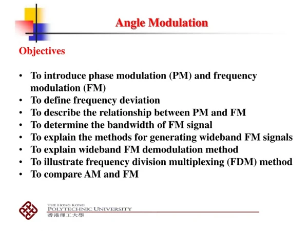
This Week • Angle Modulation • Modulation Hardware • Demodulation 57010 Communication and Control 1
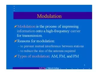
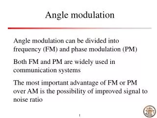
Angle Modulation In general, a carrier wave: can be modulated by changing the amplitude, frequency or phase. Frequency and phase modulation can the thought of a special cases of angle modulation. 57010 Communication and Control 1
Angle Modulation 57010 Communication and Control 1
Angle Modulation 57010 Communication and Control 1
Useful Concepts Instantaneous Frequency: Frequency Deviation: 57010 Communication and Control 1
Useful Concepts 57010 Communication and Control 1
Phase Modulation For Phase Modulation (PM) the phase is proportional to the message signal i.e. Where: is the modulating factor. 57010 Communication and Control 1
Frequency Modulation For Frequency Modulation (FM) the frequency variation is proportional to the message signal. This is equivalent to saying that the phase is proportional to the integral of the message signal: i.e.: is the modulating factor. 57010 Communication and Control 1
FM – Narrow Band We will use the expression: If Then a simplifying approximation can be made: and 57010 Communication and Control 1
FM – Narrow Band So, narrow band FM (NBFM) is very similar to AM. It has a carrier and an amplitude modulated term. Carrier AM 57010 Communication and Control 1
NBFM – Spectrum Sketch the amplitude spectrum of the NBFM signal 57010 Communication and Control 1
NBFM – Spectrum Sketch the amplitude spectrum of the NBFM signal 57010 Communication and Control 1
NBFM – Spectrum Sketch the amplitude spectrum of the NBFM signal 57010 Communication and Control 1
NBFM – Spectrum The amplitude spectrum looks the same as DSB AM 57010 Communication and Control 1
NBFM – Spectrum Let: Then: The bandwidth is the same as the bandwidth of f(t) 57010 Communication and Control 1
NBFM – Spectrum For PM: For FM: So the PM signal bandwidth is twice the message bandwidth. 57010 Communication and Control 1
NBFM – Limitations NBFM has the same power spectrum as AM-SSB and so yields only limited improvement in SNR performance. It is not used very often. Wide Band FM is used but has a much wider bandwidth e.g. ten times the message bandwidth 57010 Communication and Control 1
FM – Wide Band We will use the Taylor-Maclauren expressions: YUK! Substitute these into 57010 Communication and Control 1
FM – Wide Band 57010 Communication and Control 1
WBFM – Bandwidth [wc,wc ] [wc-3wm,wc+3wm] [wc-wm,wc+wm] [wc-2wm,wc+2wm] 57010 Communication and Control 1
WBFM – Bandwidth Why does the bandwidth grow? If the highest frequency component of f is cos(wmt) then 57010 Communication and Control 1
WBFM – Bandwidth Why does the bandwidth grow? 57010 Communication and Control 1
WBFM – Bandwidth So the spectrum of WBFM is a weighted infinite sum of signals with bandwidth i.e. of infinite bandwidth. However: the weight of each term is If then the 10th term has amplitudes 3628800 times smaller than the first term. In terms of power this is 130 dB smaller. 57010 Communication and Control 1
WBFM – Bandwidth As , the actual bandwidth used can be adjusted by choosing the modulating factor and using a finite number of terms. 57010 Communication and Control 1
NBFM Modulator A NBFM generator can be built from a few standard components: 57010 Communication and Control 1
WBFM Modulator The difference between NB and WB is the size of the modulation factor kp. A WBFM generator can be built from a NBFM generator and a multiplier. 57010 Communication and Control 1
Direct WBFM Modulator Other direct methods exist based on hardware known as Voltage Controlled Oscillators (VCOs). These are complex, non-linear devices that oscillate at a frequency proportional to an input voltage. Ming’s notes have as much as you need to know about these. 57010 Communication and Control 1
Demodulator FM->AM Differentiation of the FM signal yields an AM signal with a varying carrier frequency. Variable Carrier Amplitude After differentiation an envelope detector will complete the demodulation. 57010 Communication and Control 1
Demodulator FM->AM 57010 Communication and Control 1
Demodulator FM->AM How do you make a differentiator? A differentiator has a transfer function: You only need a device with a linear transfer function over the frequency range of the input e.g. Band Pass Filter 57010 Communication and Control 1
Demodulator Zero Crossing The number of zero crossings in an interval is proportional to the instantaneous frequency 57010 Communication and Control 1
Demodulator Zero Crossing As long as the sample time Tc is short compared to the time required for the message signal to change then: 57010 Communication and Control 1
Demodulator PLL A Phase Locked Loop (PLL) is a feedback loop where a VCO is driven to closely track an input signal. 57010 Communication and Control 1
Demodulator PLL So Vo is the FM demodulated message signal 57010 Communication and Control 1
Frequency Estimation Just ignore it. 57010 Communication and Control 1