
Transient Analysis: Understanding Circuit Response Dynamics
E N D
Presentation Transcript
C H A P T E R 5 Transient Analysis
1 0.8 0.6 0.4 0.2 0 0 0.2 0.4 0.6 0.8 1.0 1.2 1.4 1.6 1.8 2.0 t (s) (a) Transient DC voltage 1 0.5 0 – 0.5 – 1 0 0.2 0.4 0.6 0.8 1.0 1.2 1.4 1.6 1.8 2.0 t (s) (b) Transient sinusoidal voltage Figure 5.1 Examples of transient response
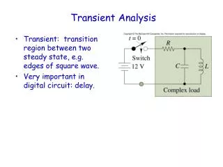
t = 0 R Switch C 12 V L Complex load Figure 5.2 Circuit with switched DC excitation
Switch R S Circuit t = 0 containing V s R L / RC combinations Figure 5.3 A general model of the transient analysis problem
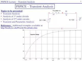
A circuit containing energy-storage elements is described by a differential equation. The differential equation describing the series RC circuit shown is di dv 1 S C + i = C dt RC dt _ v + R i R C + i R + _ v ( t ) v ( t ) C S C _ Figure 5.5 Circuit containing energy-storage element
R + + _ v ( t ) C v ( t ) S C _ dv 1 1 C – v – v = 0 RC circuit: C S dt RC RC R + _ v ( t ) i ( t ) L S L di R 1 L i – – v = 0 RL circuit: L S dt L L Figure 5.9 Differential equations of first-order circuits
t = 0 Switch Switch v V C R C B i ( t ) Exponential decay of capacitor current 1 0.9 0.8 0.7 Capacitor voltage, V 0.6 0.5 0.4 0.3 0.2 0.1 0 0 0.5 1 1.5 2 2.5 3 3.5 4 4.5 5 Time, s Figure 5.10 Decay through a resistor of energy stored in a capacitor t = 0
t = 0 i L I L R S Figure 5.15
– + i (0 ) L v ( t ) R L ( ) i t L + i ( t ) L 10 mA 0 t Figure 5.16
t = 0 R R 1 2 + v R V V C C 1 3 2 _ Figure 5.22 A more involved RC circuit
Figure 5.23 The circuit of Figure 6.45 for t > 0 + R R 1 2 v R C C 3 V V 1 2 _
R R R 1 3 2 V V / R 1 2 2 R 1 V V 1 2 + R T R R 1 2 R = R R R T 1 2 3 R T + V _ T Figure 5.24 Reduction of the circuit of Figure 5.23 to Thevenin equivalent form
R T + + V V C _ T C _ Figure 5.25 The circuit of Figure 5.22 in equivalent form for t > 0
R T + v (t) _ C L T Parallel case (a) R T L + _ v ( t ) T C Series case (b) Figure 5.39 Second-order circuits
2 1.5 x ( ) t N 1 – t e 2 0.5 e – t 1 0 0 0.1 0.2 0.3 0.4 0.5 0.6 0.7 0.8 0.9 1 t (s) Figure 5.43 Response of overdamped second-order circuit
1 0.8 0.6 x ( t ) N 0.4 – t e 0.2 – t te 0 0 0.1 0.2 0.3 0.4 0.5 0.6 0.7 0.8 0.9 1 t (s) Figure 5.44 Response of critically damped second-order circuit
t = 0 _ v ( t ) + C R _ + v ( t ) C R + + V v ( t ) L _ S i ( t ) L _ R = 5000 L = 1 H C = 1 F V = 25 V S Figure 5.46
t = 0 + C R L v ( t ) i ( t ) i ( t ) i ( t ) C R L I _ S L = 2 H C = 2 F I R = 500 = 5 A S Figure 5.48
N N 2 2 = 100 = 100 N N 1 1 N N N N 1 1 2 2 L R L , R , + + P P P P V V B B i i – – spark spark plug plug C C switch switch closed closed Figure 5.52