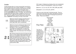
Plotting scales
Plotting scales. The type of scale used to plot ratings can dramatically affect their shape. Arithmetic scales. Logarithmic scales. The relation between water discharge and hydraulic head (h) is well known for standard artificial controls. V-NOTCH WEIR (90 degrees) Q = 2.5 h 2.5.

Plotting scales
E N D
Presentation Transcript
The type of scale used to plot ratings can dramatically affect their shape Arithmetic scales Logarithmic scales
The relation between water discharge and hydraulic head (h) is well known for standard artificial controls V-NOTCH WEIR (90 degrees) Q = 2.5 h 2.5
Here is the rating for a V-notch weir plotted using rectangular scales Concave downward = increasing differences Rating for a V-notch weir Q = 2.5 h 2.5 Hydraulic Head Water Discharge
You can use log graph paper to turn the power function Q = 2.5 h 2.5 into a straight line • Taking log of equation (Q = 2.5 h 2.5) results in • Log Q = 2.5 log h + log 2.5 • This is similar in form to equation for a straight line, which is y = mx + b • Causes relation between logarithms of Q and h to be linear. • Simpler to just plot point on log paper and let the paper convert the equation to logs.
Here is the rating for a V-notch weir plotted using logarithmic scales Rating for a V-notch weir Hydraulic Head Water Discharge
Here is how log scales are plotted Normal (Rectangular) Scales Equal distances because difference between 0 and 4 is the same as between 4 and 8 Log (0.1) = -1 Log (1) = 0 Log (10) = 1 Log Scales Equal distances because logarithms are equal distances apart
Line 3 Line 3 Line 1 Line 1 Line 2 Line 2 Here is an example of the same lines on different scale types Log Scales Rectangular Scales
You must understand what parallel lines on graphs with different scale types represent!! Problem: Determine the actual differences (in cfs) and percent differences between curves 2 and 3 and curve 1 Definitions: GH = Gage Height Q1,2,3 = Discharge from rating curve 1, 2 or 3 Q1-Q3 (Percent) = (Q1 - Q3)/Q1 Q2-Q1 (Percent) = (Q2 – Q1)/Q1
Scale offsets facilitate developing straight line rating segments Offset = 0 Offset = 4
Water Surface h We will start studying offsets by looking at the relation between water discharge (Q) and head (h) for a v-notch weir when the point of zero flow = 0 4 2.5 Q = 2.5 h 3 2.50 Gage Height 2 1 0
Here is the rating curve for a v-notch weir with the GZF set at gh = 0.0 ( head = gage height) Q = 2.5h 2.5 Gage Height Discharge
Gage Height GZF In practice gage height seldom equals head… Head = GH - GZF or about 0.37 (2.55 - 2.18)
h You must consider a scale offset when head does not equal gage height 5 2.5 h = gh – e gh – h = e Q = 2.5 h 4 3.50 Water Surface 3 Gage Height 2 1 e Scale offset 0 The offset (e) is the value used to convert GH to head!
Rating if no offset used (Gage height plotted against discharge) Rating if offset used (Head plotted against discharge) In the example just shown the rating will not be straight if gage height is plotted against discharge Gage height - e, or head Gage height Discharge
IT’S EASY!!A rating curve offset is simply a constant subtracted from the gage height so as to ensure a straight line when plotted on logarithmic paper.
Scale Offset • The offset is usually represented by “e” in equations. • Used to convert gage height to head • Will produce ratings with one or more straight line segments. This will facilitate extrapolation and interpolation of rating curves. • Can use gage height of zero flow (GZF) as first approximation of “e”.
Include velocity head The gage height of zero flow (GZF) should be measured whenever possible![The PZF (point of zero flow) is the physical location of the deepest point on the control] Gage Pool Control Section Flow Deepest point on control Gage Pool Control section perpendicular to flow
You cannot measure the GH of zero flow when channel control is in effect • Offset is the gage height of “effective zero flow” • Not the gage height of some identifiable feature • Usually determined by trial-and-error Flow
How do I figure out what the scale offset is for an existing rating? • Method 1 – • G = g.h. at bottom (beginning) of log cycle • N = 0.01 if the cycle is measuring hundredths of a foot, 0.1 cycle is measuring tenths of a foot, and so forth. • e = offset = G-N • Method 2 – • Select one complete log cycle on the gage-height scale and pick off the upper and lower values of gage height. • e = offset = ((10 x lower value) – upper value)/9
e = 0 e = 1 The shape of the curve can tell you if the offset is too high or too low Gage height e = 2 Discharge
How to select the correct offset • Johnson’s method • Compute manually • Trial and error method • Hand drawings • Can be done using program such as GRSAT
e e e = = Johnson’s method can be used to find the scale offset (G1 x G2)- G32 e = Q3 = (Q1 x Q2)1/2 (G1+ G2)- 2G3 G1 G3 Gage Height G2 Q3 Q2 Q1 Discharge
Trial and error can be used to determine the scale offset 25 E = 0 15 Stage E = 5 7 E = 7 6 Discharge