Lead Compensator design using Root Locus technique
260 likes | 558 Vues
Analysis and design of root locus alongwith lead compensator solved exmple has been introduced

Lead Compensator design using Root Locus technique
E N D
Presentation Transcript
Lead Compensator design using Root Locus technique LCS_6th Lab
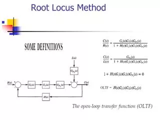
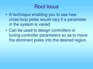
The Root Locus The Root Locus • Root locus (RL)is a graphical representation of the closed-loop poles as a system parameter (K) is varied. • RL is the study of movement (path/locus) of closed-loop poles as the gain, K, changes from 0 to ∞. • A powerful method of analysis and design for stability & transient response (Evans, 1948; 1950) • Gives the qualitative description of a control system’s performance. • Ability to provide solutions for systems having order higher than 2. • The effect of varying gain upon %OS, Ts , Tp can be displayed. • We can clearly see ranges of stability, ranges of instability & conditions that cause a system to break into oscillation.
The Root Locus Concept The Root Locus Concept
The Root Locus Concept The Root Locus Concept
The Root Locus Concept The Root Locus Concept
The Root Locus Concept The Root Locus Concept
The Root Locus Concept The Root Locus Concept
Explanation Explanation • The poles of the open-loop transfer function are easily found & do not change with changes in system gain • The tracking system of a security camera monitors pixel changes and positions the camera to center the changes.
Gain vs Pole Location Gain vs Pole Location
Gain vs Pole Location Gain vs Pole Location
Properties of the Root Locus Properties of the Root Locus
Properties of the Root Locus Properties of the Root Locus
Properties of the Root Locus Properties of the Root Locus
Properties of the Root Locus Properties of the Root Locus
Properties of the Root Locus Properties of the Root Locus
Properties of the Root Locus Properties of the Root Locus
Need of compensator Need of compensator • The purpose of compensator design using root locus methods generally is to establish a specified point in the s-plane, s = s1, as a closed loop pole. • The assumption is that time-domain transient specifications Ts & OS will be satisfied if s1 is a dominant closed-loop pole • In the simplest case, s1 is already on the root locus of the uncompensated system. The compensator is then just a gain Kc to satisfy the magnitude criterion at s1 • If point s1 is not on the uncompensated root locus, a compensator must be needed to add enough phase shift at the point s1 to satisfy the phase angle criterion. • This is done by choice of the compensators poles and zeros.
Lead compensator Lead compensator (Transient Response) (Transient Response) • In many cases, the speed of response and/or the damping of the uncompensated system must be increased in order to satisfy the specifications. • This requires moving the dominant branches of the root locus to the left, improve the systems stability & increase the speed of response. • The block diagram of lead compensator & transfer function is given as:
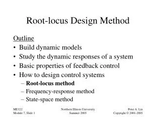
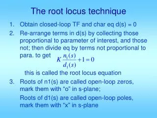
Lead compensator design procedure Lead compensator design procedure 1. From the time-domain specifications, obtain the desired location of the closed loop dominant pole s1. 2. Compute the phase shift of the plant at the chosen point s = s1. If the phase shift is an odd integer multiple of 180◦, then the selected point is on the uncompensated systems root locus for positive gain. In this case, the only compensation needed for the transient performance specifications is the proper adjustment of the gain. 3. Assuming that the selected point s1 is not already on the root locus, compute the amount of phase shift that the compensator must provide at s = s1 in order to make that point lie on the root locus. The compensators phase shift (usually) will be the shortest distance from the plants phase shift at s1 to an odd integer multiple of 180◦ for positive gain.
Lead compensator design procedure Lead compensator design procedure 4. Select the location for the compensator zero zc in such a way that following condition is satisfied |z| < |p|. 5. Locate the compensator pole so that the angle criterion is satisfied. Compute the horizontal distance from the point s = s1 to the location of the compensator pole and place the pole at that location 6. Determine the compensator gain Kc such that the magnitude criterion is satisfied in order for s1 to be a closed-loop pole. 7. If the overall response rise time, overshoot and settling time is not satisfactory, place the controller zero at a different location and repeat the procedure.
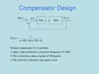
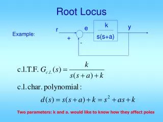
Design Example For CLS shown design a phase lead compensator to meet the following time-domain specifications 1- 2- Solution : The desired location of s1 requires the root-locus to be shifted towards the left half s plane, which requires the addition of phase lead controller