Download
1 / 28
280 likes | 338 Vues
Detailed minutes of discussions on magnetic shielding installation, NMR probe consideration, equipment layout for LEReC facility. Comprehensive overview of tests, installations for magnetic field reduction, and component fabrication progress.

E N D
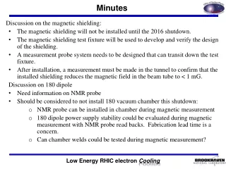
Minutes Discussion on the magnetic shielding: The magnetic shielding will not be installed until the 2016 shutdown. The magnetic shielding test fixture will be used to develop and verify the design of the shielding. A measurement probe system needs to be designed that can transit down the test fixture. After installation, a measurement must be made in the tunnel to confirm that the installed shielding reduces the magnetic field in the beam tube to < 1 mG. Discussion on 180 dipole Need information on NMR probe Should be considered to not install 180 vacuum chamber this shutdown: NMR probe can be installed in chamber during magnetic measurement 180 dipole power supply stability could be evaluated during magnetic measurement with NMR probe read backs. Fabrication lead time is a concern. Can chamber welds could be tested during magnetic measurement?
Overall Layout 64 m IP2 LEReC-I (1.6-2MeV): Gun to dump SRF gun used as a booster cavity H & V Correctors Add Quad and Skew Quad Correctors Move BPM close to 180 magnet combine with PM. Add Quad and Skew Quad Correctors
Drawing comes from VAT. • M. Mapes measured one of the new VAT valves that are in hand and found the aperture on the valve flanges on both sides in 2.480. • Mike will check with VAT on the configuration of the shielded section in the valve. • Mike B. is checking if we should be concerned about the transition from the standard tube I.D. 2.375” to the valve I.D. 2.48”.
Brahms Trailer 1002 D Racks Racks ordered on 02:00 AIP
180o Dipole Magnet Neighborhood IV BPM + YAG + Slit Assemblies HIGH FIELD SOLENOID PROFILE MONITOR LOW FIELD SOLENOID H/V Corrector ± 4.13” BPM YELLOW RHIC Beam PROFILE MONITOR EMITTANCE SLIT BLUE RHIC Beam BPM Quad/SQ Corrector kh
20o Dipole Neighborhood IV See slide #2 YELLOW RHIC Beam BLUE RHIC Beam TRANSPORT SOLENOID ERL, Profile Monitor ID=1.87” Cornell, Wire Scanner OD=1.50” ; ID=1.38’’ HIGH FIELD SOLENOID BPM PROFILE MONITOR EMITTANCE SLIT Quad/SQ CORRECTOR BPM w/ ERL Buttons ID=2.37” YELLOW RHIC Beam BLUE RHIC Beam PROFILE MONITOR 20° DIPOLE kh
BPMs in Cooling Section (14 Locations) Large Dia. BPM Housings (4.8 ID), 28mm buttons Order Placed with MPF Final Design Review 6/23/2015, no issues MPF approved to start fabrication Increased number of button first articles for 2 BPM’s one standard, one 180 magnet special MPF updated delivery schedule Agreed on vacuum bakeout for components MPF will vacuum bake buttons @900C/1hr during brazing MPF will vacuum bake housing @450C/48hr BNL will vacuum bake 1st article housing First Article delivery buttons 9/12/2015 First Article delivery housing 10/01/2015
Cooling Section Standard Profile Monitors RF impedance design approved (Peter T.) Ferrite ring mounting design complete. CMD5005 material. Requisition for commercial vacuum linear stage, requisition complete YAG screen/mirror holder design complete. Fabrication drawings for YAG screen/mirror holder and vacuum chamber. Update design for ground fingers. Stage Assembly (Linear Feedthrough) Zero Length adapter flange Profile Monitor YAG Screen Assy.
Cooling Section “hybrid” BPM, PM, Slit RF impedance analysis complete Chamber design complete Need approved fabrication drawing (CO with MPF?) Design of RF impedance grounding fingers defined Design of RF impedance ferrite configuration and mounting
Cooling Section PM meeting Notes: Mirror thickness specified Both Hybrids PM, Slit, BPM systems will be 3 position vacuum translating stage drives. The second hybrid willsubstitute the slit position (which is not needed) for a fault study beam stop. Dan transverse position accuracy of the vacuum translating stage – will order 2 and measure. Angle mount windows ordered (7 units). The windows will be coated with a thin metallic coating by the vendor (KL). The Yag crystals will be coated with a thin metallic coating to dissipate charge. Dan Steski can do it. CS has preliminary drawings for standard profile monitor for cost estimate. Need to update and check final drawings. The grounding requirements for the hybrid head has been revised. Grounding fingers and mounting frame defined. The standard profile monitor will be modified for grounding fingers in the inserted position. TBD The emittance slits needs grounding fingers – New grounding finger hardware defined.
Cooling Section Emittance Slits • Requisition for commercial vacuum linear stage. • Fabrication drawings complete and approved. • Central Shops requisition approved for vacuum chamber and W slit. • The slit needs to be grounded at the vacuum chamber when scanning. • Delivery dates: shifter, vacuum chamber, W slit, mounting hardware.
LEReC collimator thickness considerations P. Thieberger 9/8/2015 Ranges of electrons in Tungsten. The Continuous Slowing Down Approximation (CSDA) ranges obtained from the NIST ESTAR data base are distances along the electron zigzag trajectories. They exceed the penetration depth by the so called “detour factor” obtained as shown on the next slide.
LEReC collimator thickness considerations • Conclusions • For Phase 1, a collimator tungsten thickness of 0.4 mm would be adequate while 0.9 mm would be needed for Phase 2 • It would be advantageous to choose the thinnest possible material to alleviate alignment issues and to reduce slit scattering • In any case thicknesses larger than 1 mm don’t seem to be justified for this project. P. Thieberger 9/8/2015
Vacuum Hardware Beam line bellows & 180 accordion bellows purchase orders. “Standard Chamber Length” defined – NEG coating underway 180 chamber 316L vacuum annealed to 900C after welding. 180 chamber in shops, 20 chamber in shops – 2 only Test chamber welded and measured. Shielded valves on order DC Gun shielded valves and vacuum equipment.
20o Dipole Magnet Requisition approved SOW – 2 magnets by 10/1/2015. Order Placed 5/6/2015 Everson Tesla Estimated Delivery 1st two magnets 10/1/2015 Distance Between Pole Faces = 10.4 cm (4.1 in.) Magnet Vertical Gap = 10 cm Vacuum Chamber V Aperture = 9.5 cm (3.74 in.)
Compensating and Matching Solenoids Buckley magnets complete 8/20/2015?? + 6 weeks shipping + customs. Alpha Magnetics update: 1st production magnet + 9 more in house. Magnetic Measurement ordered and received 1% and 0.1% 3D probes 3D Probes being calibrated Preliminary measurements complete. Design support stand assembly – provide space for mu metal shields, separate beam pipe stand support. Fabricate Stands Magnetic shielding analysis (Wuzheng). Design prototype mu metal shields and supports - measure.
Compensating and Matching Solenoids Feed the BPM cables through a common hole in the shielding for each BPM station (4 cables /hole). This will require a 90 degree type-N connector on the LDF1-50 Heliax cable (0.37" OD) that connects to BPM button feedthrough connector. Would you have the design add the cables and connectors to the model and choose an appropriate place for the penetration, respecting the minimum cable bending radius?
Compensating and Matching Solenoids HALL PROBE / SOLENOID GRANITE TABLE (Measurement Schedule) August 3-7: complete permanent magnet measurements August 10-14: August 17-21: reconfigure Hall probe (Sullivan), then resurvey (Karl) August 24/25: Jain reviews survey data, first solenoid (Sauerwald) August 26 – Sept. 30: move solenoid granite table out of Annex October first solenoid complete, goal of 2 per week.
Compensating Solenoids Measurement We have done a preliminary scan (on-axis only) to check out the measurement system and the results seem to be good in terms of magnet performance. We tuned the main coil and bucking coil currents to match the central fields expected from Wuzheng's calculations. An adjustment of about +2% had to be made to the design currents to get the design fields. The on-axis field drops below 1 Gauss level at approximately +/- 18 cm from the magnet center. This is a faster fall off than the +/- 21 cm expected. I am not sure if the earth's field of about 0.2 Gauss is helping with this. The second field integral at the adjusted current settings comes out to be 4.019E-05 T^2.m, which meets the 4.0E-5 T^2.m requirement. Thanks, Animesh
LEReC Cooling Section Design Room LF & HF solenoid and 20o dipole magnets fabrication drawings(KH) Beam Diagnostics: BPM chamber and buttons (VDM) Beam Line 5” bellows with shields fabrication drawings (GW) 20o dipole vacuum chamber for impedence review (KH) 180o dipole fabrication drawings (KH) Spectrometer magnet (180o dipole) revisions (KH) 180o vacuum chamber + large sliding bellows fabrication drawing (KH) Beam Diagnostics ES W slit & chamber fabrication drawings (VDM) 20o dipole vacuum chamber fabrication drawings (KH) Cable tray and penetration drawings and excel sheet (AF) Beam Diagnostics: standard PM fabrication drawings (GW) Beam Diagnostics: special “hybrid” ES/PM/BPM fabrication drawings (GW) Beam line solenoid/BPM stands & vacuum chamber stand (VDM) Beam line magnetic shielding (VDM) 20o magnet stand drawing (KH) 180o magnet w/hybrid BPM stand drawings (KH) Magnetic shielding drawing and solenoid magnetic measurement test station HF dipole, quadrupole, and skew quadrupole corrector drawings
LEReC Design Room Source Design Work DC Gun Vacuum Chamber Fabrication Drawings (JH) DC Gun SF6 Pressure chamber specification control drawings (JH) DC Gun cathode cooling design for Karl S. Cornell (JH) DC Gun stands (JH) DC Gun to Booster SRF booster cavity beam line (JH) DC Gun cathode insertion drive (WJ/VDM) DC Gun cathode coating system vacuum chamber (PC) DC Gun cathode transfer load lock and vacuum chamber (WJ) Cathode production coating system design (BM)
LEReC Design Room Other Work RHIC 1:00 move real estate drawings (V.DM.) Phase 2: 5 cell cavity positioning (RM) – Revised Position on hold Phase 1 and 2 cryogenic system layout (RM) 2.1 GHz warm cavity fabrication drawings (MG) 704 MHz warm cavity fabrication drawings Transport & Merger line layout (RM/VDM) Transport & Merger Line Layout Transport & Merger Line Solenoids Transport & Merger Line BPM’s Transport & Merger Line Profile Monitors
Installation Step – 2015 Shutdown Cooling Section Purchase Orders in Place • HF and LF solenoid magnets in fabrication, 1st article in transit • Shielded vacuum valves, bellows, tuning (sliding) bellows, gauges? • Beam tubes being coated • BPM chambers and buttons ordered FDR approved • 20o merger magnets • Beamline shielded bellow and 180o magnet sliding bellows • Profile monitor and emittance slit vacuum linear drives Cooling Section Critical Items (not ordered yet) • 20o magnet vacuum chamber (MM preparing RFQ) • Special RF vacuum gaskets • Diagnostics chambers & hardware: PM, ES, PM/ES/BPM • Beamline equipment stands • 180omagnet (spectrometer magnet – moved to 2016)
Installation Step – 2015 Shutdown Punchlist Cooling Section Parts in Hand • 5 of 15 LF solenoid magnets • 5” beam tubes and flanges • Shielded vacuum valves