Download
1 / 11
110 likes | 316 Vues
Timing and fast analog memories in Saclay eric.delagnes@cea.fr. Saclay’s microelectronics group. 6 designers. Main Fields Of interest : Low Noise, Low Power Front-ends for capacitive Detectors. Analog Memories (Very High Speed and High dynamic range).

E N D
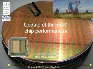
Timing and fast analogmemories in Saclayeric.delagnes@cea.fr
Saclay’s microelectronics group • 6 designers. • Main Fields Of interest : • Low Noise, Low Power Front-ends for capacitive Detectors. • Analog Memories (Very High Speed and High dynamic range). • Large dynamic range front–end for nuclear physics. • MAPS for High Energy Physics • Use of conservative CMOS technologies (0.25-0.35 µm). • Applications for all the physics divisions of DAPNIA .
Timing experience in DAPNIA ??? • No experts at all on very fast timing in DAPNIA. • But a little background concerning the 100ps-1ns resolution range. • Mainly small parts of complex chips. • 2 kinds of design: • ramp generator T.A.C. with external ADC. • DLL based TDC. • In most of the case : deadtime.
MATE/ATHED chip for Nuclear Physics. • Common chip for the readout of Si,SiLi,Csi detectors of the hodoscop of the MUST2 experiment (GANIL). • 16 channels, 14 bit dynamic range. • 0.8µm CMOS • Leading edge discriminator • Track&hold for energy measurement. • Voltage ramp for Time (of flight measurement). • Performances: 600ns range <240 ps FWHM resolution (6MeV proton) in proc of IEEE 2003 /NSS Portland Oct 2003.
Time interpolator of the MATACQ chip. • MATACQ = multiGHz, high dynamic range analog memory. • Heart of the « pipeline » circuit used in a handheld oscilloscope. • used in the MATACQ (V2719) board industrialized by CAEN. • A standard problem on oscilloscopes: how to avoid the jitter of the trace when triggered asynchronously • Solution: to measure the time between the trigger and the clock. • Achieved by a ramp based time interpolator: • 50 ns range. • 15 ps steps. • <15 ps rms “noise” jitter. • total of < 50 ps rms jitter (incl. NL) on the whole system (mainly due to digital coupling in the trigger signal outside the chip).
Fine Time measurement in the ARS Chip (ANTARES) Timestamp: • Counters + 2 voltage ramps in FlipFlop • <200ps rms resol. • low dead time IEEE Trans.Nucl.Sci.49:1122-1129,2002
Using Analog Sampling solution for Timing measurement Techniques for timing Measurement using sampling. Can deal with heavy pile-up. • using FIR filter: • Multiple sampling in ATLAS ATLAS: W. Cleland, NIM A 338 (1994) Resol < 500ps Fs=40 MHz, 12 bits. • ANTARES: Resol < 200ps Fs=700MHz, 6 bits. • Fit : • DEMIN: ~50ps rms. Fs= 2 GHz 12 bits M. Houry NIMA A 557 (2006) 648–656 • DVCS/E00 @ CEBAF P. Bertin DVCS/E00-110 experiment : Final Readiness Report. • Digital CFD : resol ~100ps Fs=100MHz 12 bits L. Bardelli NIM A A 521 (2004) 480–492. => resolution can be 10-100 times smaller than the sampling period.
Fast analog memories • Well known principle (since early 90s): • fast sampling of the analog signal on a switched capacitor array. • Slowest readout (eventually multiplexing)and digitization. • Low power but need « external » trigger • Dead Time. • Sampling speed increased over GHz ( with old technologies) by two techniques: The sampling DLL (ARS) Matrix sampling DLL: higher bandwitdh and better time precision (MATACQ, SAM)
The single ramp ADC revisited • Principle: increase the speed of ramp ADC by measuring time with DLL-based TDC without power penalty. Performances for the timing measurement (extracted from those of the ADC): • Dynamic range > 12 bits • Time step 320ps • jitter < 30 ps rms • NLD < +/-45 ps in proc of IEEE 2006/NSS San Diego Oct 2006
Fast Analog Memories in DAPNIA Prospective AFTER : 05-06 TPC T2K 72 ch/ 512 pts Fe= 1-50 Mhz,BP = 10 Mhz Dyn= 10 bits AMS0.35 µm. Also includes FE. New Architectures ARS0 : 97-98 ANTARES/HESS1 5 ch/ 128 pts Fe= 1Gs/S BP = 80 Mhz Dyn~8-9bits AMS 0.8 µm ARS1 : 98-04 ANTARES 4 Ch system on chip including ARS0 KM3Net CTA HAMAC : 93-97 Calo ATLAS 12 canaux/ 144 pts Fe= 40 Mhz BP = 10 Mhz Dyn= 13,6 bits DMILL 0.8 µm SAM 04-05 HESS2 2 ch / 256 pts Fe= 50 MHz-2GHz BP = 300 Mhz Dyn= 12 bits AMS 0.35 µm MATACQ : 99-01 Matrix Structure 1 ch, 2560 pts Fe= 50 MHz-2GHz BP = 300 Mhz Dyn= 12 bits AMS 0.8 µm (PATENT) MATACQ 2 Fs~ 5-10GHz , BW>600MHz >5000 pts ? DSM technology PIPELINE :01- 02 METRIX 1 ch Système on chip integrating 1 MATACQ Technologically feasible Collaborationswith l’ IN2P3/ LAL
Performances of the recent designs (MATACQ & SAM) • MATACQ: 0.8µm (Breton, TNS VOL. 52, NO. 6, DEC 2005 ) • SAM: 0.35µm (Delagnes, NIMA567:21-26,2006) • Max sampling freq. 2.5 GHz. • 150 mW/ch (SAM) • Voltage dynamic range 12-13 bits. • Xtalk >0.3%. • Bandwidth 300 MHz. • Sampling jitter : 20 ps rms. • On recent (future) chips, efforts made on the readout speed (66 MHz on SAM) and input Bandwidth. SAM: HESS2 PMT-like pulse sampled @ 1GS/s: In black single acquistion. In grey 1000 superimposed acquisition. timing precision (<20ps rms) MATACQ