AC Circuits
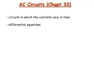
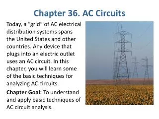
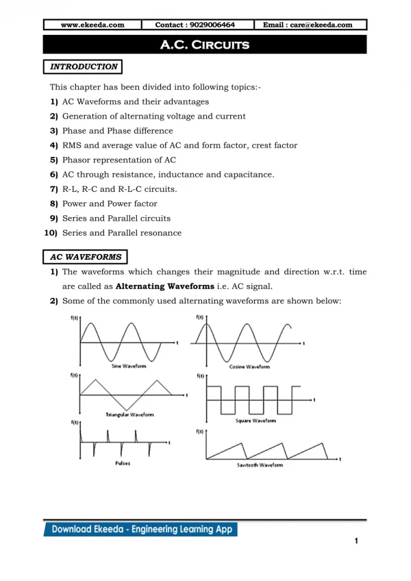
AC Circuits. Chapter 23. AC Circuits. Capacitive Reactance Phasor Diagrams Inductive Reactance RCL Circuits Resonance. Resistive Loads in AC Circuits. Ohm’s Law : R is constant – does not depend on frequency No phase difference between V and I. Capacitive Reactance.

AC Circuits
E N D
Presentation Transcript
AC Circuits Chapter 23
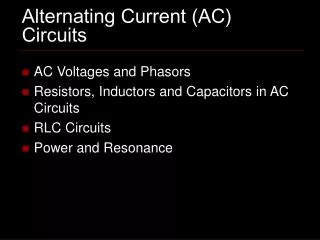
AC Circuits • Capacitive Reactance • Phasor Diagrams • Inductive Reactance • RCL Circuits • Resonance
Resistive Loads in AC Circuits Ohm’s Law: • R is constant – does not depend on frequency • No phase difference between V and I
Capacitive Reactance At the moment a capacitor is connected to a voltage source: • Current is at its maximum • Voltage across capacitor is zero
Capacitive Reactance After a long time, the capacitor is charged: • Current is zero • Voltage is at its maximum (= supply voltage)
Capacitive Reactance Now, we reverse the polarity of the applied voltage: • Current is at its maximum (but reversed) • Voltage hasn’t changed yet
Capacitive Reactance Time passes; the capacitor becomes fully charged: • Current is zero • Voltage has reversed to match the applied polarity
Capacitive Reactance Apply an AC voltage source: • an AC current is present in the circuit • a 90° phase difference is found between the voltage and the current
Capacitive Reactance We want to find a relationship between the voltage and the current that we can use like Ohm’s Law for an AC circuit with a capacitive load: We call XC the capacitive reactance, and calculate it as: units of capacitive reactance: ohms (W)
Capacitive Reactance A particular example:
Capacitive Reactance • Power is zero each time either the voltage or current is zero • Power is positive whenever V and I have the same sign • Power is negative whenever V and I have opposite signs • Power spends equal amounts of time being negative and positive • Average power over time: zero
Capacitive Reactance • The larger the capacitance, the smaller the capacitive reactance • As frequency increases, reactance decreases • DC: capacitor is an “open circuit” and • high frequency: capacitor is a “short circuit” and
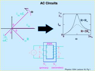
Phasor Diagrams Consider a vector which rotates counterclockwise with an angular speed : This vector is called a “phasor.” It is a visualization tool.
Phasor Diagrams For a resistive load: the current is always proportional to the voltage
Phasor Diagrams For a capacitive load: the current “leads” the voltage by p/2 (or 90°)
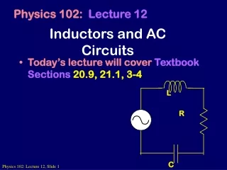
Inductive Reactance A coil or inductor also acts as a reactive load in an AC circuit.
Inductive Reactance For a coil with a self-inductance L:
Inductive Reactance As the current increases through zero, its time rate of change is a maximum – and so is the induced EMF
Inductive Reactance As the current reaches its maximum value, its rate of change decreases to zero – and so does the induced EMF
Inductive Reactance The voltage “leads” the current in the inductor by p/2 (or 90°)
Inductive Reactance The inductive reactance is the Ohm’s Law constant of proportionality: units of inductive reactance: ohms (W)
Inductive Reactance The voltage-current relationship in an inductive load in an AC circuit can be represented by a phasor diagram:
Inductive Reactance Mnemonic for remembering what leads what: “ELI the ICEman” EMF (voltage) EMF (voltage) current (I) inductor (L) capacitor (C) current (I)
Inductive Reactance • Larger inductance: larger reactance (more induced EMF to oppose the applied AC voltage) • Higher frequency: larger impedance (higher frequency means higher time rate of change of current, which means more induced EMF to oppose the applied AC voltage)
RCL Circuit Here is an AC circuit containing series-connected resistive, capacitive, and inductive loads: The voltages across the loads at any instant are different, but a common current is present.
RCL Circuit The current is in phase with voltage in the resistor. The capacitor voltage trails the current; the inductor voltage leads it. We want to calculate the entire applied voltage from the generator.
RCL Circuit We will add the voltage phasors as vectors (which is what they are.) We start out by adding the reactive voltages (across the capacitor and the inductor). This is easy because those phasors are opposite in direction. The resultant’s magnitude is the difference of the two, and its direction is that of the larger one.
RCL Circuit Now we use Pythagoras’ Theorem to add the VL – VC phasor to the VR phasor.
RCL Circuit The current phasor is unaffected by our addition of the voltage phasors. It now makes an angle f with the overall applied voltage phasor.
RCL Circuit We can make Ohm’s Law substitutions for the voltages:
RCL Circuit Our result: suggests an Ohm’s Law relationship for the combined loads in the series RCL circuit: Z is called the impedance of the RCL circuit. SI units: ohms (W)
RCL Circuit -- Power If the load is purely resistive, the average power dissipated is We can use the phasor diagram to relate R to Z trigonometrically: “power factor”
RCL Circuit -- Resonance Series-connected inductor and capacitor:
RCL Circuit -- Resonance Energy is alternately stored in the capacitor (in the form of the electrical potential energy of separated charges) and in the inductor (in its magnetic field). When the magnetic field collapses, it charges the capacitor; when the capacitor discharges, it builds the magnetic field in the inductor.
RCL Circuit -- Resonance This “LC oscillator” or “tuned tank circuit” oscillates at a natural or resonant frequency of
RCL Circuit -- Resonance At the resonant frequency, how are the inductive and capacitive reactances related? The reactances are equal to each other.
RCL Circuit -- Resonance At the resonant frequency, when the inductive and capacitive reactances are equal, what is the situation in the circuit?
RCL Circuit -- Resonance At the resonant frequency, when the inductive and capacitive reactances are equal, what is the impedance of the circuit? At resonance, the circuit’s impedance is simply equal to its resistance, and its voltage and current are in phase. If the resistance is small, the current may be quite large.