Register-Transfer (RT) Synthesis
Register-Transfer (RT) Synthesis. Greg Stitt ECE Department University of Florida. Introduction. Register-transfer (RT) synthesis Definition: Synthesis from register transfer level (RTL) descriptions VHDL, Verilog typically describe circuits as connections of RTL components

Register-Transfer (RT) Synthesis
E N D
Presentation Transcript
Register-Transfer (RT) Synthesis Greg Stitt ECE Department University of Florida
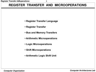
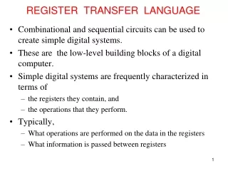
Introduction • Register-transfer (RT) synthesis • Definition: Synthesis from register transfer level (RTL) descriptions • VHDL, Verilog typically describe circuits as connections of RTL components • What are register-transfer level components? • Muxes, ALUs, registers, multipliers, etc. • One abstraction level above gates • Basically, components you use in most structural descriptions • What are other levels? • Transistor level • Gate level • Register transfer level • High level • System level • Etc.
RT Synthesis • Main Steps • Lex/Parsing • Analyzes HDL, converts into intermediate representation • Resource Allocation • Maps intermediate representation into RT components • Optimizations • Logic minimization • State minimization • State encoding • Etc. • Technology Mapping • Placement + Routing
Technology Mapping • Converts circuit from one technology (e.g. gates) onto technology used by physical device (e.g. LUTs, CLBs, etc) CLB CLB CLB CLB CLB CLB
Placement • Input: Technology-mapped circuit • For simplicity, just consider CLBs • Technology-mapped circuit consists of “virtual” CLBs and “virtual” connections • FPGA fabric consists of physical CLBs • Simplified Placement Definition: • Map “virtual” CLBs onto physical CLBs • I.e. Decide on a location in the FPGA for each virtual CLB Technology Mapped Circuit FPGA Fabric Possible Placement 1 2 3 4 CLB CLB CLB CLB CLB CLB 1 2 3 4 5 CLB 6 CLB CLB CLB CLB CLB CLB CLB 6 5 CLB CLB CLB CLB CLB CLB CLB CLB CLB CLB
Routing • Input: A set of placed components, and a list of “virtual” connections • Simplified Routing Definition: • Determine how to configure routing resources to implement “virtual” connections 1 2 3 4 CLB 1 2 3 4 Physical CLBs not connected – must configure routing resources to implement these connections: 5 CLB 6 CLB CLB 6 5 CLB CLB CLB CLB CLB
Placement+Routing (PAR) • Placement and routing highly dependent • Placement affects how well circuit can be routed • Example: Placement 1 Placement 2 6 3 CLB 1 CLB 1 2 3 4 CLB 1 2 3 4 CLB CLB 4 CLB CLB 5 CLB 6 CLB CLB 6 5 2 CLB CLB CLB 5 CLB CLB CLB CLB CLB Clearly, placement 1 is easier to route
Placement+Routing (PAR) • Goals: • 1) Make sure circuit can be implemented on fabric • Trivial for placement, difficult for routing • Bad placement may make circuit unroutable • 2) Minimize delay of critical path • Critical path is the longest register to register delay • Important - Determines clock speed of circuit • Why is placement and routing important? • Bad PAR = slow circuit • Even worse, BAD PAR = no circuit Placement 2 Placement 1 6 3 CLB 1 CLB 1 2 3 4 CLB CLB CLB 4 CLB CLB 5 CLB 6 CLB CLB 2 CLB CLB CLB 5 CLB CLB CLB CLB CLB Even if routing is possible, placement 2 likely to have longer wires – slower clock
Placement • Problem: Find a placement for each CLB, such that routing can maximize clock speed • Challenges: • 1) Huge solution space! • Tiny Example: Fabric = 100 physical CLBs, Circuit = 10 “virtual” CLBs • Possibilities = 100! / 90! = 6.2 * 1019 • And, that is for a tiny fabric and tiny circuit!!!!!!!!!!! • Guess what … placement is NP-Complete • 2) How to know how good the routing will be? • One (im)possibility - perform routing for each possible placement • Tiny example, cont. - assume same number of routing possibilities as placement possibilities • 6.2 * 1019 *6.2 * 1019 = A BIG NUMBER! • Routing is also NP-complete • Cleary, placement needs to estimate quality of routing • Estimate known as a cost function
Cost Function Examples • Example: average wire length • Motivation: short wires faster than long wires • Not perfect - many short wires not on critical path may lead to inaccuracy • i.e. critical path may still be long despite short average wire length • How to determine wire length? • Without routing, don’t know length • Possibilities: • 1) Euclidian distance - measure straight line distance between CLBs • Ignores how wire would be routed (can’t route diagonals) • 2) Manhattan distance - shortest “zig-zag” distance • Includes bends between CLBs Euclidian Distance CLB CLB CLB CLB CLB CLB CLB CLB CLB Manhattan Distance CLB CLB CLB CLB CLB CLB CLB CLB CLB
Placement Techniques • Placement is an NP-complete optimization problem • Many possible placements, we want the best one • What does this suggest for a solution? • Remember last lecture! • 1) Branch and bound • Likely not feasible • 2) Map to other NP-complete problem - use heuristic for that problem • 3) Use general optimization heuristics • Simulated annealing (very common) • Hill climbing • How to use general optimization heuristics? • Cost function represents quality of placement • Neighboring solution – try new location for a “virtual” CLB, swap 2 CLBs, etc.
Placement Techniques • Also common to map placement to other NP-complete problems • Example: Min-cut problem • Background: Given a graph, a cut is a set of edges that divides the graph into two (or more) groups • Min-cut problem definition: • Find the minimum cut size for a given graph • Similar to graph bipartitioning problem Cutsize = 5 Cutsize = 3
Placement Techniques • How can graph bipartitioning/min-cut be used for placement? • Graph: Nodes are CLBs, Edges are wires • Partition divides FPGA into sections • Goal: minimize communication between sections • Bipartitioning attempts to reduce routing “congestion” • i.e. Cost function is cut size • We can use common heuristic for graph bipartitioning • Kernighan-Lin (KL) Heuristic
Placement Techniques • KLFM Heuristic (Kernighan-Lin Fiduccia-Mattheyses) • Basic Idea: • Start with initial partition • Iteratively improves cutsize • Cutsize is number of edges between partitions • Moves one node at a time • Node that gives greatest reduction or least degradation • Lock node after moving • Continue moving nodes until all locked or size constraints are violated • Find best partitioning, unlock all nodes • Repeat until no improvement found
KLFM Algorithm Initial Partition Maximum Size = 4 Size = 3 Size = 3 Cutsize = 5
KLFM Algorithm Maximum Size = 4 Size = 4 Size = 2 Cutsize = 3
KLFM Algorithm Maximum Size = 4 Size = 3 Size = 3 Cutsize = 2
KLFM Algorithm Maximum Size = 4 Size = 2 Size = 4 Cutsize = 2
KLFM Algorithm Maximum Size = 4 Size = 3 Size = 3 Cutsize = 4
KLFM Algorithm Maximum Size = 4 Size = 2 Size = 4 Cutsize = 4
KLFM Algorithm Maximum Size = 4 Size = 3 Size = 3 Cutsize = 5
KLFM Algorithm Backtrack to minimum cut size, unlock nodes, and repeat Size = 3 Size = 3 Cutsize = 2
Circuit Partitioning • How does a partition help us place CLBs? • Apply bipartitioning hierarchically – circuit partitioning • Basic idea • 1) Initially divide FPGA into 2 sections • Execute bipartitioning to determine which section “virtual” CLBs get mapped into • 2) Divide each section into 2 subsections • Execute bipartitioning to determine which subsection “virtual” CLBs get mapped into • 3) Divided each subsection into 2 subsubsections • And so on
Placement Summary • Definition: Map “virtual” CLB onto physical CLBs, such that routing can maximize clock frequency • Need way of estimating routing quality – cost function • Wire length • Typically leads to shorter wires, but may cause congestion • Cutsize • Helps with congestion, but may result in long wires • Existing approaches are typically a combination • NP-Complete Optimization Problem • Can use many existing heuristics • Simulated annealing, KL are common
Routing • Definition: Given a placement and a set of “virtual” connections, implement connections using routing resources such that clock speed is maximized • i.e Figure out how to configure connection boxes and switch boxes in most efficient way • Clearly another optimization problem • Huge number of possible routing solutions, we want the best one • Routing is NP-Complete • What does this suggest? • 1) Branch and bound • Likely not feasible • 2) Map to other NP-complete problem - use heuristic for that problem • 3) Use general optimization heuristics • Simulated annealing • Hill climbing • Genetic algorithms • Etc.
Routing: Background • Routing algorithms sometimes performed in 2 stages • Global and detail routing • Global routing determines channels to be used for each connection (“net”) • Ignores low-level details of C/S boxes • Focuses on finding a short paths that minimize congestion • Detail routing determines low-level connections used by each C/S box • Uses coarse route provided by global router • Analogy: Driving directions • Global routing: Take 34th to Archer to 13th, etc. • Detailed routing: Get in the right lane, wait at the light, turn left, change into the right lane, etc.
Maze Routing • Input: • Grid structure representing routing resources • Each box represents a terminal or a routing resource • Set of source and destination terminals • Defines end points of each connection • Problem definition: Find the shortest route for each pair of source and destination terminals Each box is either a terminal or a routing resource
Maze Routing • Heuristic: • 1) Expansion – find shortest path from src to dest that avoids used resources • Done using breadth first search • Essentially determines shortest distance of each box from the source, until the dest is found Terminals 2 2 1 2 1 1 2 2 1 2
Maze Routing • Heuristic, Cont.: • 2) Traceback – Follow path from dest with decreasing labels (shortest path to src) • May be multiple paths • 3) Repeat 1+2 for each net • Really good animation at: • http://foghorn.cadlab.lafayette.edu/MazeRouter.html
Maze Routing • Another example • Main Weakness: • Quality of routing depends on ordering of nets • How to determine best ordering? • Too many possibilities, generally not feasible Routing blue before purple gives shorter wire length
1 1 1 1 1 1 2 1 1 1 congestion Pathfinder • Pathfinder [Ebeling, et al., 1995] • Introduced negotiated congestion • Ordering independent • During each routing iteration, route nets using shortest path • Allows overuse (congestion) of routing resources • If congestion exists (illegal routing) • Update cost of congested resources based on the amount of overuse • Rip-up all routes and reroute all nets 2
Versatile Place&Route (VPR) • Versatile Place&Route (VPR) [Betz] takes as input a description of the fabric • Describe routing resources, etc. • Could potentially be used for many FPGAs – “versatile” • 2 variations of VPR • Routability driven – find an implementation that uses the fewest routing resources • Timing driven – maximize clock speed • Placement/routing technique • Modified version of Pathfinder • Uses cost function based on fabric description • Details: http://www.eecg.toronto.edu/~vaughn/vpr/vpr.html
Summary • RT Synthesis creates circuit from RT-level description • 3 important steps – Technology mapping, Placement, Routing • Technology mapping converts gate-level (or other level) representation to CLBs, DSPs, etc. • Placement finds a physical CLB for each mapped CLB • Routing configures routing resources to connect CLBs • Placement and Routing are NP-Complete • Need heuristics • Placement – Simulated annealing, KL, etc. • Routing – Maze, Pathfinder, VPR