Download
1 / 57
580 likes | 1.02k Vues
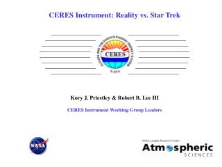
CERES Instrument: Reality vs. Star Trek Kory J. Priestley & Robert B. Lee III CERES Instrument Working Group Leaders. Components of the Earth’s Radiative Energy Budget. CERES Instrument. Design is based upon the Earth Radiation Budget Experiment (ERBE) philosophy

E N D
CERES Instrument: Reality vs. Star Trek Kory J. Priestley & Robert B. Lee III CERES Instrument Working Group Leaders
CERES Instrument • Design is based upon the Earth Radiation Budget Experiment (ERBE) philosophy • Instrument was designed, manufactured and tested by TRW (Redondo Beach, CA) • Contains three sensor assemblies with cassegrain optics and thermistor bolometer detectors • Sensors measure thermal radiation in the near-visible through far-infrared spectral region • Three sensor channels are coaligned and mounted on a spindle which rotates about the elevation axis • Hemispherical sampling obtained with an azimuthal axis drive system • Channel fields of view overlap by <98% • On-board calibration capability
Launch Configuration (CERES Stowed) Mission Configuration (CERES Deployed) Aqua Spacecraft
EOS -AQUA 02:54:58 PDT May 04, 2002 Vandenberg AFB
Single Orbit of CERES Aqua Data (Polar Orbit, Rotating Azimuth Mode)
Aqua First Light Images June 22, 2002 Reflected Solar Flux Emitted Thermal Flux
Fabricate instrument Process Data and Produce Data products Launch Satellite & Achieve Orbit Integrate Satellite & Instruments Receive Data from Instruments Fabricate Satellite Remote Sensing Experiment Lifecycle
CERES Instrument • Design is based upon the Earth Radiation Budget Experiment (ERBE) philosophy • Instrument was designed, manufactured and tested by TRW (Redondo Beach, CA) • Contains three sensor assemblies with cassegrain optics and thermistor bolometer detectors • Sensors measure thermal radiation in the near-visible through far-infrared spectral region • Three sensor channels are coaligned and mounted on a spindle which rotates about the elevation axis • Hemispherical sampling obtained with an azimuthal axis drive system • Channel fields of view overlap by <98% • On-board calibration capability
CERES Instrument • Design is based upon the Earth Radiation Budget Experiment (ERBE) philosophy • Instrument was designed, manufactured and tested by TRW (Redondo Beach, CA) • Contains three sensor assemblies with cassegrain optics and thermistor bolometer detectors • Sensors measure thermal radiation in the near-visible through far-infrared spectral region • Three sensor channels are coaligned and mounted on a spindle which rotates about the elevation axis • Hemispherical sampling obtained with an azimuthal axis drive system • Channel fields of view overlap by <98% • On-board calibration capability
INCIDENT RADIATION Epoxy 815Z Sealing Layer 4 mm Black Paint layer 10.6 mm Platinum Leads 1.0 x 10⁻³ in. Diameter Thermistor 15 mm Kapton 0.3 x 10 -3 in. 2024-TB51 Aluminum Disk Thin Layers of Epoxy 815Z Detail of a CERES Flight Detector Can sense temperature changes at the micro-Kelvin level….
Wheatstone Bridge C1 A1 +Vout +Vbias R11 R14 R16 3 Comp. Bol. R6 R8 7 R4 R2 10 R12 5 R9 A3 R15 2 1 R5 A4 9 A5 -Vout R7 R10 Act. Bol. R1 R3 8 4 6 -Vbias R13 A2 11 CERES Detector Bridge Amplifier Circuit
CERES Instrument • Design is based upon the Earth Radiation Budget Experiment (ERBE) philosophy • Instrument was designed, manufactured and tested by TRW (Redondo Beach, CA) • Contains three sensor assemblies with cassegrain optics and thermistor bolometer detectors • Sensors measure thermal radiation in the near-visible through far-infrared spectral region • Three sensor channels are coaligned and mounted on a spindle which rotates about the elevation axis • Hemispherical sampling obtained with an azimuthal axis drive system • Channel fields of view overlap by <98% • On-board calibration capability
Fixed Azimuth Plane Scanning (FAPS) Rotating Azimuth Plane Scanning (RAPS) Surface Scan Patterns
Fixed Azimuth Plane Scanning (FAPS) Rotating Azimuth Plane Scanning (RAPS) Surface Scan Patterns WHY FAPS & RAPS?
Fixed Azimuth Plane Scanning (FAPS) Rotating Azimuth Plane Scanning (RAPS) Surface Scan Patterns WHY FAPS & RAPS? Answer: Angular Models
What the heck is an Angular Model??? For a single footprint, the CERES sensors only measure the amount of energy leaving the top of the atmosphere in a given direction….
What the heck is an Angular Model??? For a single footprint, the CERES sensors only measure the amount of energy leaving the top of the atmosphere in a given direction…. What we need to know is the TOTAL energy leaving the atmosphere in all directions for a single footprint……
What the heck is an Angular Model??? For a single footprint, the CERES sensors only measure the amount of energy leaving the top of the atmosphere in a given direction…. What we need to know is the TOTAL energy leaving the atmosphere in all directions for a single footprint…… Angular Models, R, convert, or scale, a directional quantity (what we measure) to a hemispherical quantity (what we need)!
Case A: Perfect light Bulb B v R = 1 C v A v R = 1 R = 1 Thought Experiment… Light Bulb!!
Case B: Dirty light Bulb B v R = 1 C A v v R > 1 R < 1 Thought Experiment… Light Bulb!!
Fixed Azimuth Plane Scanning (FAPS) Rotating Azimuth Plane Scanning (RAPS) So, Why RAPS and FAPS….. FAPS instrument provides uniform spatial coverage for optimal Earth Radiation Data Products…. RAPS instrument data is used to develop Angular Models….
CERES Instrument • Design is based upon the Earth Radiation Budget Experiment (ERBE) philosophy • Instrument was designed, manufactured and tested by TRW (Redondo Beach, CA) • Contains three sensor assemblies with cassegrain optics and thermistor bolometer detectors • Sensors measure thermal radiation in the near-visible through far-infrared spectral region • Three sensor channels are coaligned and mounted on a spindle which rotates about the elevation axis • Hemispherical sampling obtained with an azimuthal axis drive system • Channel fields of view overlap by <98% • On-board calibration capability
Why is Calibration Accuracy Important? • Accurate and useful monitoring of the Global climate requires instruments that very accurately measure small perturbations about a relatively large mean value. • An instantaneous doubling of atmospheric CO2 would produce a temporary change in TOA flux of ~4 W/m2. (~4 to 8 counts) • Apparent change in Earth emitted radiation from ERBE to CERES of ~4W/m2 on decadal scale (Science, Feb 02, 2002). • Both of these events represent a change in the mean signal of ~ 2%. • To adequately measure these events a signal-to-noise ratio of at least 2:1 is required, leading to absolute accuracy requirements at the sub 1% level. • The CERES instruments are the most highly calibrated and characterized Earth Radiation Budget instruments to have ever flown…
Why is Calibration Accuracy Important? • Accurate and useful monitoring of the Global climate requires instruments that very accurately measure small perturbations about a relatively large mean value. • An instantaneous doubling of atmospheric CO2 would produce a temporary change in TOA flux of ~4 W/m2. (~4 to 8 counts) • Apparent change in Earth emitted radiation from ERBE to CERES of ~4W/m2 on decadal scale (Science, Feb 02, 2002). • Both of these events represent a change in the mean signal of ~ 2%. • To adequately measure these events a signal-to-noise ratio of at least 2:1 is required, leading to absolute accuracy requirements at the sub 1% level. • The CERES instruments are the most highly calibrated and characterized Earth Radiation Budget instruments to have ever flown…
International Standard Solar Constant Photodiode Monitor Traceability Blackbodies Solar Lamps Sources Window Channel Total Channel Shortwave Channel Radiometric Channel Deep Convective Clouds Tropical Mean Terra/TRMM Common VZ, SZ CERES On-orbit Calibration Philosophy Supplemental Validation Studies
CERES Onboard Calibration Sources Internal Calibration Module (ICM) • Blackbodies for the Total and Window channels • Temperature knowledge obtained via Platinum Resistance Thermometers (PRTs) • Quartz-halogen tungsten lamp for the Shortwave channel • ICM Provides 3 unique radiance levels for the SW and LW sources
CERES Solar Calibration • Mirror Attenuator Mosaic • The MAM is a Solar Diffuser plate which attenuates direct solar view • Fabricated from a Nickel substrate with Aluminum coated spherical cavities or divots • Forward baffles limit Field-of-View to ± 4-degrees, prohibiting stray light contamination • Provides a Relative calibration of the Shortwave channel and the SW portion of the Total channel
Radiometric Calibration Facility • Narrow Field of View Blackbody (NFBB) is primary standard (Emissivity of greater than 0.9999) • 12.5 cm Wide Field of View Blackbody (WFBB) • Cold Space Reference (CSR) blackbodies • New SW reference source (SWRS) with minimum LW variations and better spectral characterization • 5 cm i.d. integrating sphere with associated optics • Cryogenically cooled Transfer Active Cavity Radiometer (TACR) • Point Response Function characterization source • Constant Radiance Reference to determine scan dependent offsets • Earth infrared radiation simulators • Liquid nitrogen cooled shroud wall
0.2 - 2.5 mm 2.5 - >100 mm SWRS Fourier Transform Spectrometer CERES Proto Flight Model Edition 2 End-to-End Spectral Response
Characterize and calibrate the instrument spectrally, spatially and radiometrically Responsible for ensuring instrument performance is in consonance with all science objectives Continually looking at ways to improve measurement technology to maximize scientific return Long term goal is to minimize the dichotomy between science and engineering Instrument Working Group