Sequential Circuit Analysis
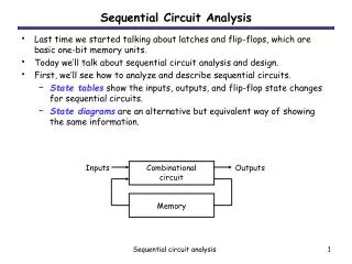
Inputs. Combinational circuit. Outputs. Memory. Sequential Circuit Analysis. Last time we started talking about latches and flip-flops, which are basic one-bit memory units. Today we’ll talk about sequential circuit analysis and design.

Sequential Circuit Analysis
E N D
Presentation Transcript
Inputs Combinational circuit Outputs Memory Sequential Circuit Analysis • Last time we started talking about latches and flip-flops, which are basic one-bit memory units. • Today we’ll talk about sequential circuit analysis and design. • First, we’ll see how to analyze and describe sequential circuits. • State tables show the inputs, outputs, and flip-flop state changes for sequential circuits. • State diagrams are an alternative but equivalent way of showing the same information. Sequential circuit analysis
Combinational circuit Outputs Memory Inputs An example sequential circuit • Here is a sequential circuit with two JK flip-flops. There is one input, X, and one output, Z. • The values of the flip-flops (Q1Q0) form the state, or the memory, of the circuit. • The flip-flop outputs also go back into the primitive gates on the left. This fits the general sequential circuit diagram at the bottom. X Z Q0 Q1 Sequential circuit analysis
How do you analyze a sequential circuit? • For a combinational circuit we could find a truth table, which shows how the outputs are related to the inputs. • A state table is the sequential analog of a truth table. It shows inputs and current states on the left, and outputs and next states on the right. • For a sequential circuit, the outputs are dependent upon not only the inputs, but also the current state of the flip-flops. • In addition to finding outputs, we also need to find the state of the flip-flops on the nextclock cycle. Sequential circuit analysis
Analyzing our example circuit • A basic state table for our example circuit is shown below. • Remember that there is one input X, one output Z, and two flip-flops Q1Q0. • The present state Q1Q0 and the input will determine the next state and the output. Sequential circuit analysis
The outputs are easy • The output depends on the current state – Q0 and Q1 – as well as the inputs. • From the diagram, you can see that Z = Q1Q0X Output at the current time Sequential circuit analysis
Flip-flop input equations • Finding the next states is harder. To do this, we have to figure out how the flip-flops are changing. Step 1: Find Boolean expressions for the flip-flop inputs. I.e. How do the inputs (say, J & K) to the flipflops depend on the current state and input Step 2: Use these expressions to find the actual flip-flop input values for each possible combination of present states and inputs. I.e. Fill in the state table (with new intermediate columns) Step 3: Use flip-flop characteristic tables or equations to find the next states, based on the flip-flop input values and the present states. Sequential circuit analysis
Step 1: Flip-flop input equations • For our example, the flip-flop input equations are: J1 = X’ Q0 K1 = X + Q0 J0 = X + Q1 K0 = X’ • JK flip-flops each have two inputs, J and K. (D and T flip-flops have one input each.) Sequential circuit analysis
Step 2: Flip-flop input values • With these equations, we can make a table showing J1, K1, J0 and K0 for the different combinations of present state Q1Q0 and input X. J1 = X’ Q0 J0 = X + Q1 K1 = X + Q0 K0 = X’ Sequential circuit analysis
Step 3: Find the next states • Finally, use the JK flip-flop characteristic tables or equations to find the next state of each flip-flop, based on its present state and inputs. • The general JK flip-flop characteristic equation is: Q(t+1) = K’Q(t) + JQ’(t) • In our example circuit, we have two JK flip-flops, so we have to apply this equation to each of them: Q1(t+1) = K1’Q1(t) + J1Q1’(t) Q0(t+1) = K0’Q0(t) + J0Q0’(t) • We can also determine the next state for each input/current state combination directly from the characteristic table. Sequential circuit analysis
Step 3 concluded • Finally, here are the next states for Q1 and Q0, using these equations: Q1(t+1) = K1’Q1(t) + J1Q1’(t) Q0(t+1) = K0’Q0(t) + J0Q0’(t) Sequential circuit analysis
Getting the state table columns straight • The table starts with Present State and Inputs. • Present State and Inputs yield FF Inputs. • Present State and FF Inputs yield Next State, based on the flip-flop characteristic tables. • Present State and Inputs yield Output. • We really only care about FF Inputs in order to find Next State. • Note: the outputs occur this cycle and the next state in the next cycle Sequential circuit analysis
1/0 10 00 1/0 01 11 0/0 0/0 0/0 0/0 1/1 1/0 State diagrams • We can also represent the state table graphically with a state diagram. • A diagram corresponding to our example state table is shown below. input output state Sequential circuit analysis
0/0 1/0 10 00 1/0 1/1 01 11 0/0 1/0 0/0 0/0 Sizes of state diagrams • Always check the size of your state diagrams. • If there are n flip-flops, there should be 2n nodes in the diagram. • If there are m inputs, then each node will have 2m outgoing arrows. • From each state • In our example, • We have two flip-flops, and thus four states or nodes. • There is one input, so each node has two outgoing arrows. A B D C Sequential circuit analysis
Example Sequential circuit analysis
10 00 11 01 Example Sequential circuit analysis
0/0 10 00 1/0 0/0 0/1 01 11 1/0 1/0 1/0 0/0 Example 1 Sequential circuit analysis
Sequential circuit analysis summary • To analyze sequential circuits, you have to: • Find Boolean expressions for the outputs of the circuit and the flip-flop inputs. • Use these expressions to fill in the output and flip-flop input columns in the state table. • Finally, use the characteristic equation or characteristic table of the flip-flop to fill in the next state columns. • The result of sequential circuit analysis is a state table or a state diagram describing the circuit. Sequential circuit analysis