Download
1 / 99
990 likes | 1.03k Vues
High-Speed Digital Logic. Chris Allen (callen@eecs.ku.edu) Course website URL people.eecs.ku.edu/~callen/713/EECS713.htm. Properties of high-speed gates. Circuit families and their characteristics Logic circuits within a family share certain characteristics logic levels supply voltages

E N D
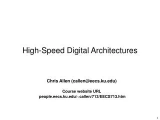
High-Speed Digital Logic • Chris Allen (callen@eecs.ku.edu) • Course website URL people.eecs.ku.edu/~callen/713/EECS713.htm
Properties of high-speed gates • Circuit families and their characteristics • Logic circuits within a family share certain characteristics • logic levels • supply voltages • rise and fall times • maximum clock frequency for sequential logic devices • power dissipation • The output drive circuits determine several of these characteristics • The most common logic families • GaAs BJT circuits are being developed. • GaAs circuits are faster due to its superior electron mobility • Other properties of GaAs: generally radiation hard; no natural oxide; brittle
Properties of high-speed gates VHI = 4 V & 50- term IOUT = 80 mA
Properties of high-speed gates • Comparison of logic families • Note: Quiescent power dissipation < power dissipation at 1 MHz clock frequency for CMOS and BiCMOS. • Due to the energy dissipated during charging and discharging the load capacitance each clock cycle. • Energy dissipated while charging capacitor: 0.5 CVcc2 • Energy dissipated while discharging capacitor: 0.5 CVcc2 • Total energy dissipated per cycle: CVcc2 • The power dissipation is Pdiss(f) = f C Vcc2 for a switching frequency f. • Pdiss is essentially frequency independent for TTL, ECL, and GaAs as it is not due to capacitive charging/discharging, rather it is due to the internal circuits.
Properties of high-speed gates • To illustrate this point consider the circuit below as we look at the energy required to charge and discharge the capacitor. • Assume the capacitor is initially discharged,Vc = 0 V • Assume at t = 0 the switch moves to position Athe capacitor begins to charge.During the charge interval • The energy drawn from source V1 is • Once charged, the energy stored in the capacitor is • Half of the energy drawn from the source is dissipated as heat during the charging interval; the remainder is dissipated during discharge.
Logic circuit details • CMOS • VDD: supply voltage(2 to 10 V) • VSS: ground • Capacitive input • Totem-pole output driver • Pulls output up or pulls output down • Only one transistor active at a time • Low quiescent power • Output transistor has relatively low ON-state resistance • 35 to 100 in ON state (24 to 64 mA output capacity for FACT) • and high OFF-state resistance (500 M) • Output driver stage
Logic circuit details • TTL and BiCMOS • VCC: supply voltage (5 V) • Resistive input • Totem-pole output driver • Dissipates power in both HI and LO quiescent modes due to bias currents • Low output resistance in both states (HI/LO) • Rs < 10
Logic circuit details • BiCMOS • VCC: supply voltage (5 V) • Capacitive input • CMOS internal logic • TTL output driver • Dissipates power in both HI and LO quiescent modes due to bias currents • Frequency-dependent power dissipation due to CMOS • Low output resistance in both states (HI/LO) • Rs < 10
Logic circuit details • ECL • VEE: supply voltage (-5 V) • VCC: ground • Resistive input • Emitter-follower output • Open emitter output • Terminated off chip • Large output current capacity • Dissipates power in both HI and LO quiescent modes due to bias currents • Low output resistance in HI state Rs < 10 • High output resistance in LO state ~ open circuit
Logic circuit details • GaAs (MESFET) • VEE: supply voltage (-5 V) • VSS: supply voltage (-3.4 V) • VDD: ground • Resistive input • Source-follower output • Open source output • Terminated off chip • Large output current capacity • Dissipates power in both HI and LO quiescent modes due to bias currents • Low output resistance in HI state Rs~ 8 • High output resistance in LO state ~ open circuit
Logic circuit details • ECL and GaAs use a similar output drive circuit design • ECL output stage GaAs output stage • Neither use totem-pole design • Both require off-chip biasing • Both support wired-OR logic
Logic circuit details • Termination schemes • ECL and GaAs logic families require termination using resistors connected to a negative voltage to complete the circuit. • This approach requires a -2 V supply • An alternative approach forms the Thevenin equivalent from chip supply voltage, VEE
Logic circuit details • Termination schemes • Select values for R1 and R2 so that • • and • using 5% resistor values. • For VEE = -5.2 V, R1 = 130 , R2 = 90 • which produces, RT = 53 and VTT = -2.1 V
Logic circuit details • Faster technologies cost more • In terms of $ • In terms of Pdiss • In terms of design complexity • Don’t use technology with more capability than needed • Recall that Tr Fknee • Fknee = 0.5 / TrBandwidth over which signal fidelity must be preserved • More reflections, ringing • More crosstalkhigher dI/dt increases inductive crosstalkhigher dV/dt increases capacitive crosstalk • Therefore, use technology with the slowest acceptable Tr
Logic circuit details • Faster devices require terminations • these dissipate power as well • Power dissipation for termination resistors • For ECL and GaAs logic • VHI≈ -0.8 V, VLO ≈ -1.8 V • The power dissipated in the terminating 50- resistor is • Every signal must be terminated. • For a large number of signals, about half will be HI at any instant.
Logic circuit details • For circuits of moderate complexity • May have 100s of signals • 100 x 15 mW 1.5 W = Pdiss in terminations • 100 x 14 mA 1.4 A = ITT from the –2-V power supply • Note that 1/8-W termination resistors are adequate in this configuration • Now consider the alternate configuration • Average power dissipated / signal = 141 mW (vs. 15 mW for –2-V source) • 14 W for circuit with 100 signals • 130- termination resistor must be rated for ¼ W
Noise margins • Digital-signal transmission has superior signal preservation compared to analog transmission • Digital signaling has “built-in” tolerance to noise, crosstalk, voltage variations, ringing or reflections, temperature variations, EMI, and other sources of signal distortion … • as long as bit errors can be avoided. • To avoid bit errors, a transmitted HI must be reliably received as a HI, and similarly a transmitted LO, received as a LO • Digital communication can tolerate limited channel error sources due to noise margins • The difference between the transmitted signal level and the decision threshold level is the noise margin. • As long as a logical HI signal is above a given threshold level,it will be read as a HI, likewise for LO signals.
Noise margins • Noisy digital waveform • Ringing • Eye diagram showing signal’s statistical distribution
Noise margins • Input considered HI if VI > VIH • Input considered LO if VI < VIL • Gate HI output is between VOH(max) & VOH(min) • Gate LO output is between VOL(max) & VOL(min) • Data on a device’s input and output parameters are provided in the vendor’s data sheet. • VOH(minimum, typical, maximum) output voltage HI • VOL(minimum, typical, maximum) output voltage LO • VIH,VILthreshold for deciding if input signal is HI or LO • The noise margin is computed from these parameters • Noise margin: NMH = VOH(min) – VIH • NML = VIL – VOL(max)
Noise margins • Noise margins are sometimes expresses as % of signal range • Note: These are worst case values to yield the smallest (most conservative) noise margins.
Logic circuit details • Combinational logic and sequential logic • For combinational logic, the output depends on the state of the inputs now, i.e., it has no memory • Examples include – AND, OR, XOR, NOR, NAND gates • The output of sequential logic depends on the state of the inputs now and on the previous input states, i.e., it does have memory • Examples include – flip-flops, shift registers, counters, etc. • D flip-flop shift register counter
Logic circuit details • Combinational devices are characterized by propagation delay • Sequential devices are characterized by propagation delay plus setup and hold requirement on data and minimum pulse duration (width)
Timing analysis • High-speed designs require timing analysis that includes • Propagation delays through devices • Propagation delays through interconnects (traces) • Data setup times • Data hold times • Pulse durations • Reliable designs anticipate worst case conditions • To find the elapsed time as a signal propagates through a signal path, individual propagation delays are added. • In clocked (sequential) systems, the signal must arrive and be stable for the required time before the clock edge arrives. • In some designs, multiple signal paths must be analyzed to determine the circuit’s highest operating frequency.
Timing analysis • Timing analysis example #1 • Consider the circuit as shown with flip-flop specifications given below. • The D flip-flop triggers on the rising clock edge. • Find the maximum clock frequency for reliable operation for: • a) Case where trace delay is 0 s • b) Case where trace delay is 200 ps • Flip-flop, AC electrical characteristics (temperature from -25 ºC to + 55 ºC)
Timing analysis • Timing analysis example #1 • The D flip-flop triggers on the rising clock edge. • This circuit outputs a square-wavewhose frequency is fCLK/2. • The maximum propagation delay from the rising clock edge to the signal S1 at the D input for case (a) is 1.9 ns. • Add 0.8 ns to satisfy the setup (TS) requirement. • Therefore the minimum clock period is 1.9 + 0.8 = 2.7 ns, or fCLK(max) = 371 MHz
Timing analysis • Timing analysis example #1 • For case (b) the maximum propagation delay from the rising clock edge to the signal S1 at the D input is propagation delay is 1.9 ns + 0.2 ns, or 2.1 ns • Again add 0.8 ns to satisfy the setup (TS) requirement. • Therefore the minimum clock period is 2.1 + 0.8 = 2.9 ns, or fCLK(max) = 345 MHz • Notes:Signal rise time is not a factor • The 500-MHz fmax specification is not a factor unless timing analysis result indicates higher clock frequency than flip-flop can support
Timing analysis • Timing analysis example #2 • A circuit consisting of ECL flip-flops is configured as shown below.This circuit produces two output signals in phase quadrature with frequencies one-fourth that of the input clock frequency.The AC specifications for the flip-flop are detailed in the table.Unless specified otherwise, the delay through each of the interconnecting traces is 200 ps. • Determine the maximum, worst-case clock frequency that this circuit can operate over the full temperature range for the circuit. • Flip-flop, AC electrical characteristics (temperature from -25 ºC to + 55 ºC)
Timing analysis • Timing analysis example #2 • Analyze each signal path to determine which one limits the overall max operating frequency. • Signal S3: Minimum clock period 2.1 + 0.8 = 2.9 ns (from previous example) • Delay from CLOCK to stable signal S8: 1.9 + 0.2 + 1.9 + 0.2 = 4.2 ns • Add required setup time: 4.2 + 0.8 = 5 ns • 300-ps clock delay to 3rd flip-flop: Minimum clock period 5 - 0.3 = 4.7 ns • Delay from CLOCK to stable signal S11: 1.9 + 0.2 = 2.1 ns • Add required setup time: 2.1 + 0.8 = 2.9 ns • 100-ps relative clock delay between 3rd and 4th flip-flops: • Minimum clock period 2.9 - 0.1 = 2.8 ns • Longest minimum clock period: 4.7 ns fmax = 213 MHz
Logic circuit details • Circuit schematics • Each component assigned a unique identifier • Capacitors: C1, C2, C3, … • Diodes: D1, D2, D3, … • Inductors: L1, L2, L3, … • Integrated circuits: U1, U2, U3, … • Resistors: R1, R2, R3, … • Switches: SW1, SW2, SW3, … • Transformers: T1, T2, T3, … • Transistors: Q1, Q2, Q3, … • Component values are specified (e.g., R1 150 ) • Each integrated circuit pin number is shown • Each signal is labeled with unique signal name • Power and ground connections are identified
Homework #2 • Pseudo-random noise (PRN) generator circuit design • Random, or even psuedo-random, serial bit streams are useful in various systems (radar, digital communication, cryptography, etc.) • Mathematically well-understood process for producing “random” sequence with relatively long repeat period • Digital PRN implementation involves shift register outputs fed back through exclusive-OR gates
Homework #2 • Pseudo-random noise (PRN) generator circuit design • Pattern generation • For feedback from 3rd and 4th • shift-register taps, a 21-state PRNpattern is produced, after which thepattern repeats
Homework #2 • Pseudo-random noise (PRN) generator circuit design • Critical timing analysis • focuses on one clock cycle • used to determine maximum clocking frequency • For this feedback configuration, a 127-state PRN pattern is produced
Homework #2 • Pseudo-random noise (PRN) generator circuit design • Perform design using 5 different technologies • FACT (National Semiconductor Advanced CMOS: 74AC devices in DIP package) • FAST TTL (Texas Instruments F series TTL: 74F devices in DIP package) • 100K ECL (Fairchild 300 series ECL: DIP package) • 10G GaAs (GigaBit Logic 10G series: the fastest version in type “C” package) • UPG GaAs (NEC Logic) • Involves timing analysis • Estimating currents to be supplied by each power supply • List of materials • does not include power supplies, signal generators, printed-circuit boards • Complete schematic diagrams for CMOS and ECL circuits • include pin numbers, signal names, termination resistors when required • For each of the 5 designs, determine • if high-speed design rules should be applied • maximum usable clock frequency • Requires careful reading of data sheets
Homework #2 • Pseudo-random noise (PRN) generator circuit design • Common mistakes to avoid • unspecified inputs or unused inputs • improper “programming” of shift register • too few or too many termination resistors on a signal line • incomplete schematics (missing reference designators on resistors and integrated circuits, missing pin numbers on integrated circuits) • using incorrect component parameters (wrong package or temperature) • Do’s and don’ts • do not use the built-in XOR gate found in the GigaBit Logic shift register • tie unused CMOS and TTL input high or low, do not let them float • floating ECL and GaAs inputs are interpreted as logical LO • grounded input interpreted as logical HI with ECL and GaAs
High-speed gate packaging issues • Key issues regarding packaging • Package inductance • Lead capacitance • Heat transfer • Cost, reliability, testability
High-speed gate packaging issues • Package inductance • Inductance in the signal path from the integrated circuit chip (die) to the printed-circuit board (PCB) due to • wire bonds (typically 1-mil diameter gold wires) • package leads • Amount of inductance varies with geometry
Ground bounce • Package inductance can cause ground bounce • Inductance in the ground pin and its wire bond cause ground bounce • Consider the current flow as the load capacitor, C, is discharged • Inductance between the die and ground cause the die’s ground reference to fluctuate when the ground current varies • This variation in the on-chip ground reference is ground bounce • LO-to-HI transition as • capacitor discharges
Ground bounce • Mathematically, it can be shown that (assuming a Gaussian pulse as described in Appendix B with t3 = 0.281) • where V is the nominal voltage change between logical LO and HI • This affects the on-chip reference level used to interpret the input level • VGND is affected by the output driver but the effect may show up on the input section
Ground bounce • Note that this phenomenon is not observable outside the chip
Ground bounce • Approaches to reduce ground bounce • Recall that • Therefore to reduce VGND • Increase Tr (if possible) • Decrease V (often not an option) • Decrease C (should be reduced already) • Reduce LGND (how?) • Provide parallel paths (multiple ground pins) • Use wider conductors (bond with ribbons instead of wire) • Shorter path between the chip and the PWB (e.g., surface mount)
Ground bounce • Other techniques to reduce ground bounce • In ECL and GaAs devices, the output stage is isolated from the rest of the circuit • VCC1 and VCC2 (VDDO and VDDL) are not connected on the chip • These two pins are to be connected to GND on the PWB • Another approach is to transmit differential signals rather than single-ended signals (reduced impact of VGND) • single-ended signaling • differential signaling
Lead capacitance • Mutual capacitance, CM, between adjacent pins can result in crosstalk • Mutual capacitance is most significant when an output pin is adjacent to an input pin • In this case crosstalk coupling from output to input may result in performance errors • To reduce this effect – • Reduce the capacitance, C r Area / Distance • Increase separation distance larger package size • Smaller geometries • Increase Tr (if possible) • Don’t put input and output pins side by side, isolate with Vcc or GND pins
High-speed gate packaging issues • Examples of integrated circuit packages • Variations in: • Overall package size • number of pins • maximum die size • Pins geometry • through-hole vs. surface mount • pin spacing (pitch) • perimeter vs. area array • Plastic vs. ceramic package material • hermeticity • thermal properties • cost
High-speed gate packaging issues • Typical reactances of integrated circuit packages • Lead Adjacent lead Packageinductancecapacitance • 14-pin DIP 8 nH 4 pF • 68-pin LCC 7 nH 7 pF • wire bond 1 nH 1 pF • solder bump 0.1 nH 0.5 pF • Other considerations in selecting package type: • package cost • # of I/O (signal density) • product testability at speed • chip (die) size • environmental requirements – hermeticity • heat transfer (more on this topic later)
High-speed gate packaging issues • Package types • Dual-in-line • Single-in-line • Pin-grid array • Small outline • Thin SOP • Quad flat pack • Small outline J-lead • Quad flat J-lead • Quad flat nonleaded • Tape carrier • Ball-grid array • Land-grid array
High-speed gate packaging issues • Package-less options • Package-less involves dealing with bare die used in multichip modules (MCMs), chip on board (COB), and other processes • Motivation • reduced cost • reduced size / volume • integrated circuit technology trends • various die sizes • growing # of I/O • increased power dissipation • Chip on board • Multichip module