Download
1 / 10
100 likes | 246 Vues
FEA of Coil Supports. J Bessuille June 2013 – Oct 2013 . 1. Create a composite beam that represents the geometry of the coils (copper + GFRP). Filler: “Generic GFRP”; E=49 GPa. 2. Simulate that beam to determine the deflection under simple boundary conditions.

E N D
FEA of Coil Supports J Bessuille June 2013 – Oct 2013
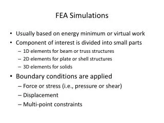
1. Create a composite beam that represents the geometry of the coils (copper + GFRP) Filler: “Generic GFRP”; E=49 GPa 2. Simulate that beam to determine the deflection under simple boundary conditions 3. Use linear elastic model to determine effective stiffness, Eeff Eeff = 89.5 GPa
Load Path: Coil Blocks Plates Strongback No Contact between coil and clamp plate No Contact between coil and strongback Horizontal: 0.354 mm 12.9 deg from vertical – 0.359 mm
More realistic supports – Clamped Ends • Added 8” extra depth to spine of stongback to counterbalance new boundary condition • This brings the overall diameter of the 7 coil+carrier assemblies to ~60” • This is a workable concept that will be further detailed and analyzed. Horizontal: 3.73 mm 12.9 deg from vertical: 1.14 mm
Compare clamped ends to kinematic 6-strut support X + Y Phi + Z X + Y Note: Both end pins co-axial. All 3 pin axes intersect predicted CG of coil+carrier assembly
BASELINE 7 carrier end faces fixed End spider fixed, rigid First pass at analyzing Frame On Floor Hanging Fixed 6 top beam nodes Beam Elements Solid Elements Fixed 2 bottom end surfaces Fixed 2 top end surfaces
Crane Fixed 4 top beam nodes Quick check of stresses in beams: Worst case while lifting with crane
Baseline deflection Hanging deflection • Why are the floor and hanging deflections so similar? The main difference between the models is that with the hanging condition, the upper z-beams are supported along their length, while for the floor condition, only the frame ends are supported. Looking at the reaction forces for the hanging case, we see that the vertical load carried by the z-beams is more than an order of magnitude less that that supported by the ends. Beam rxn= (2.88+2.47)e3 N = 545 kgf End rxn = (3.51+3.44)e4 N = 7085 kgf Hanging reactions
Hanging • Right: The highest stress was seen at the DS end of the hanging condition. At 92.6 MPa, it is well below the yield strength of 6061-T6 (275 MPa) but is still an area of concern. Because the mesh size here is relatively coarse (compared to salient dimensions of the parts), further studies should refine the mesh in these areas. • Left: A look at the strain at the DS end shows a great deal of twisting on the fingers and heptagon supports. Since these members transfer the coil end support conditions (i.e. slope) to the frame, reducing strain here will improve overall deflection. Increasing torsional stiffness should reduce twisting • The beam stresses are very low (-3.0 – 2.3 MPa) in the hanging and floor-supported models. This is because the ends of the frame, where the coil load is borne, are directly supported by either the vacuuim chamber (hanging) or the ground (floor). It is likely some of these members can be made smaller / thinner.