KEK Test Beam Phase II Plan
60 likes | 177 Vues
This document outlines the experimental plan for the MICE FT workshop held at Daresbury in August 2005, led by Makoto Yoshida from Osaka University. It provides a detailed layout for T585's Step 1 and Step 2, focusing on high momentum parallel beam studies without a magnetic field, light yield checks, and tracking performance evaluations with a solenoid magnetic field. Challenges, calibration plans, and operational timelines are also discussed, including the successful commissioning of the Cryostat and accelerator tuning to initiate the physics run.

KEK Test Beam Phase II Plan
E N D
Presentation Transcript
KEK Test BeamPhase II Plan Makoto Yoshida (Osaka Univ.) MICE FT workshop @ Daresbury 2005/8/30
Step 1 • High momentum parallel beam without magnetic field • Check light yield • 3HF dependence • 2500 ppm / 5000 ppm on the 4th station • Angle dependence • Dead channel (efficiency) • Cross talk between fibers / views • Position alignment • Station alignment • fiber alignment on station • High speed DAQ ~1kHz is necessary
Step 2 • With solenoid magnetic field • Study tracking performance • Defocused beam in f30cm • Low momentum beam 0.2 – 0.6 GeV/c • Select muons by TOF/ACC • Measure muon momentum by TOF • sT1=50ps, shodoscope=60ps sTOF=66ps • 300 MeV/c dp/p = 1.7% • 400 MeV/c dp/p = 2.8% • Difficulties • decay in flight • path length on spiral track in magnetic field • energy loss
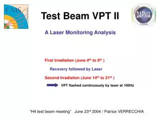
Preparation works • TOF • Establish calibration / online monitoring scheme • Improve support structure for easy manipulation • ACC • Establish calibration with LED • gain monitoring in beam time • DAQ • temperature monitor logging • AFE slow control • Quick VLSB readout
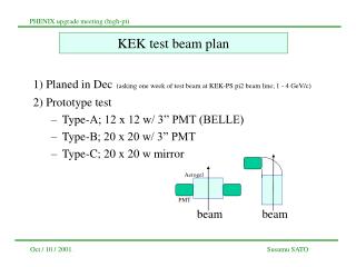
Time line • July, 2005 • KEK-PS T585 has been approved for 1 week beam time (20 shifts) at KEK-PS p2 beam line • Aug. 24th • Start to prepare VLPC Cryostat in p2 experimental area • Successful operation of Cryocooler • Reach 7K • Sep. 1st • Infrastructure in p2 area • Stable operation of Cryostat • Sep. 5th • Slow control by Linux • AFE initialization • Temperature control • VLSB readout in UniDAQ framework • Around Sep. 12th • Cosmic-ray test • establish trigger scheme • test DAQ system • Around Sep. 21th • Place solenoid magnet • Move Cryostat beside solenoid • Sep. 27th– Sep. 30th • Accelerator tuning • Sep. 30th • Start physics run • Could be delayed to Oct. 3rd, if accelerator needs more tuning