Panasonic Communications Co., Ltd.
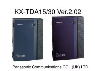
KX-NCP0158 (8ch DECT IP-CS) Technical information (Edition-1). Panasonic Communications Co., Ltd. “. IP-CS Concept - 1. 8ch IP DECT Cell Station. - Designed to extend system feature to DECT handsets - Wireless solution for remote office communication.

Panasonic Communications Co., Ltd.
E N D
Presentation Transcript
KX-NCP0158 (8ch DECT IP-CS) Technical information (Edition-1) Panasonic Communications Co., Ltd.
“ IP-CS Concept - 1 8ch IP DECT Cell Station • - Designed to extend system feature to DECT handsets • - Wireless solution for remote office communication. • - Provides 8 call user connections over 10/100Mbit LAN • - No special cabling required (overcomes distance issue) • - Powered by POE remotely • - Simplifies installation for TDE & NCP • - No Activation Key requirements. • - One DSP (DSP-4, -16, -64) card is needed. • - Compatible with “Legacy” CS’ TDA0141/TDA042and TDA0158.
“ IP-CS Concept - 2 Remote office-1 • Seamless Hand over between TDA0141/0142/0158 and IP-CS • - Roaming KX-NCP MPR 2.0 KX-TDE MPR 3.0 DSP (4/16/64) is needed. LAN Network Local office Remote office-2 Seamless Hand over Roaming Ext.100 Ext.100
Contents - Introduction - System Capacity - VoIP Channel Capacity - Hand over - Air Synchronization - Installation
“ Introduction -1 Specifications
“ System Capacity -1 The KX-NCP0158 connects other device via DSP voice channels (Need DSP resources). The KX-NCP0158 is installed into Virtual Slot. One Slot supports 4 x KX-NCP0158.
“ System Capacity -2 Sample: NCP500 One Slot supports 4 x KX-NCP0158. Room A Room B Remote-A Remote-B Remote-C Remote-D Remote-E Remote-F
“ VoIP Channel Capacity - 1 DSP Resource KX-DT3xx IP-Trunk DSP IP-Trunk Traditional IP-CS KX-NCP0158 IP-Ext. KX-NTxx The IP-CS does not support Peer to Peer connection mode. →Need DSP resource
“ VoIP Channel Capacity - 2 DSP Resource (Cont.) Need DSP resource KX-DT3xx IP-Trunk DSP IP-Trunk Traditional IP-CS KX-NCP0158 IP-CS KX-NCP0158 The IP-CS does not support Peer to Peer connection mode.
“ VoIP Channel Capacity - 3 DSP Resource (Cont.) Need DSP resource KX-DT3xx IP-Trunk DSP IP-Trunk Traditional IP-CS KX-NCP0158 The IP-CS does not support internal connection mode.
“ VoIP Channel Capacity - 4 DSP Resource (Cont.) DSP Power
“ VoIP Channel Capacity - 5 The number of simultaneous telephone calls through IP-CS. (Sample : NCP500/1000 MPR 2.0) [Restriction Key]
“ VoIP Channel Capacity - 6 The number of simultaneous telephone calls through IP-CS. (Sample : NCP500/1000 MPR 2.0) [Restriction Key]
“ Handover - 1 Present Path Handover (Start) KX-DT3xx IP-Trunk DSP IP-Trunk Traditional IP-CS-1 KX-NCP0158 IP-CS-2 KX-NCP0158 Handover CS-1 to CS-2.
“ Handover - 2 Present Path Handover (During Hand over) Handover Path KX-DT3xx IP-Trunk DSP IP-Trunk Traditional 1- Keep hand over DSP resource 2- Synchronize packet CS-1 and CS-2 IP-CS-1 KX-NCP0158 IP-CS-2 KX-NCP0158 Require DSP spare resource Connect Both CS during handover.
“ Handover - 3 Handover (Cut over) New Path KX-DT3xx IP-Trunk DSP IP-Trunk Traditional 1- Cut over 2- Release hand over DSP resource IP-CS-1 KX-NCP0158 IP-CS-2 KX-NCP0158
“ Handover - 4 Present Path Handover (If No-DSP resource) KX-DT3xx IP-Trunk DSP IP-Trunk Requests DSP resource Traditional If there is no hand over DSP resource IP-CS-1 KX-NCP0158 IP-CS-2 KX-NCP0158 Hand over does not perform. There is no major/minor error information. Connect Both CS during handover.
“ Handover - 5 ASCII Command Log data, If DSP resource is not enough. ASCII Command : “PSDSP” may help investigation. MPR>PSDSP Last Num : 80 ← The newest log starting log number. No. Time Extno Logno Slot/Port Cause [001] 07/09/20 11:37:00 00402 21000007 08/00 01/03 [002] 07/09/21 11:37:00 00402 21000005 00/03 02/04 [128] 07/09/21 11:37:00 00402 21000005 00/03 02/04 1 2 3 4 5 6 1. Log number. 2. Logged Time 3. PS Extension number 4. PS internal data 5. Connected IPCS slot/port 6. Cause of log.
Air Synchronization (Basic technology)
“ Air Synchronization (Basic technology) - 1 Please understand the technology of DECT. Otherwise, we cannot understand the technology of Air Synchronization. The DECT signal consists of a transmitting frame (TX) and a receiving frame RX). And the composition of each frame (TX/RX) is as follows. Time Slot Frequency US-DECT is not supported Time decomposition “Time Division Multiplex” TX/RX Sequence Frequency Euro: f0-f9 US: f0-f4 TX TX RX RX
“ Air Synchronization (Basic technology) - 2 One CS is connecting 1 x DECT-PS The one communication DECT signal consists of two control channels (D) and one voice channel (V). Sample (Control channel always uses even number frames. ) TS3 TS3 TX TX TS0 (D) , TS2 (D), TS3 (V)
“ Air Synchronization (Basic technology) - 3 One CS is connecting 2 x DECT-PS If a CS is connecting 2 x DECT-PS, data channels and voice channel consist as follows, Sample The data channels (D) is the common data for both DECT-PS. The voice data is separated by the time slots. E.g. TS-3 and TS-4 TS3 TS3 TX TX No collision TS4 TS4
“ Air Synchronization (Basic technology) - 4 One CS is connecting 8 x DECT-PS If a CS is connecting 8 x DECT-PS, data channels and voice channel consist as follows, Sample
“ Air Synchronization (Basic technology) - 5 Super frame synchronization (Wired Connection) Internal Clock PRI/BRI The same DECT Sync-Clock on the cable-1 and the cable-2. System Clock Sync-Clock Sync-Clock DECT Sync-Clock Cable-1 Cable-2 CS-1 signal CS-2 signal are synchronized. PLL PLL Super frame synchronization CS-1 CS-2 Seamless handover is possible.
“ Air Synchronization (Basic technology) - 6 Super frame synchronization (Wired Connection) When two or more CS are installed closely together, all the CS use different control channels. Sample D-1 D-2 CS-1 CS-2 DECT-PS can find CS by receiving D-Channel. Unless both CS-1 and CS-2 have synchronization, the DECT-PS cannot find any CS other than the CS it is already connected to.
“ Air Synchronization (Basic technology) - 7 Super frame synchronization (Wired Connection) When two or more sets of CS are installed in closely, all the CS uses different control channels. Sample D-1, V-1 D-2, V-2 CS-1 CS-2 During handover (CS-1 to CS-2) the DECT-PS is communicating to two CSs.
Air Synchronization (IP-CS)
“ Air Synchronization (IP-CS) - 1 Super frame synchronization (WirelessConnection) Internal Clock PRI/BRI No- Sync-Clock System Clock DSP Sync-Clock Sync-Clock DECT Sync-Clock Cable-1 How to synchronize ? PLL PLL CS-2 KX-NCP0158 CS-1
“ Air Synchronization (IP-CS) - 2 Super frame synchronization (WirelessConnection) Internal Clock PRI/BRI System Clock DSP Sync-Clock DECT Sync-Clock Slave-CS Cable-1 D-1 D-2 PLL PLL PLL Master-CS IC-CS picks up D channel signal from other CS CS-2 KX-NCP0158 CS-1 Air Synchronization
“ Air Synchronization (IP-CS) - 3 Super frame synchronization (WirelessConnection) DSP Master-CS Slave-CS D-1 D-2 PLL Internal Clock IC-CS picks up D channel signal from other CS CS-1 KX-NCP0158 CS-2 KX-NCP0158
“ Air Synchronization (IP-CS) - 4 Legacy CS (KX-TDA0141/TDA042/TDA0158) A Legacy CS will receive its timing and synchronisation from the PBX, therefore TDA0141/TDA0142 and TDA0158 must be CS-Master. IP-CS (Mater) An IP-CS configured as CS-Master will create and send out its own timing and synchronisation. IP-CS (Slave) An IP-CS configured as CS-Slave will receive timing and synchronisation from either a legacy CS or IP-CS set to CS-Master
“ Air Synchronization (IP-CS) - 5 Super frame synchronization (WirelessConnection) Master Slave Slave Slave DSP Level Level-1 Level-2 Level-3,4 Level-5 Max.5 Levels Seamless handover Area Master Slave Slave Slave Internal Clock DSP Level Level-1 Level-2 Level-3,4 Level-5 Max.5 Levels
“ Air Synchronization (IP-CS) - 6 Super frame synchronization (WirelessConnection) Master Slave Master Slave Internal Clock DSP Level Level-1 Level-2 Level-1 Level-2 Handover is not possible between a Legacy CS-Master and an IP-CS Master Seamless handover Area Master Slave Master Slave Internal Clock Internal Clock DSP Level Level-1 Level-2 Level-1 Level-2 Handover is not possible between an IP-CSMaster and an IP-CS Master
“ Air Synchronization (IP-CS) - 7 Super frame synchronization (WirelessConnection) Synchronization Seamless handover Area Local office Remote office CS-2 CS-6 CS-1 CS-5 Internal Clock CS-3 CS-7 DSP CS-4 CS-8 Handover Sample: CS-2 ↔ CS-3 CS-3 ↔ CS-4 CS-2 ↔ CS-4 Handover Sample: CS-6 ↔ CS-7 CS-7 ↔ CS-8 CS-6 ↔ CS-8
“ Air Synchronization (IP-CS) - 8 Super frame synchronization (WirelessConnection) Synchronization Seamless handover Area CS-3 CS-1 CS-4 DSP CS-2 CS-5 Handover Sample: CS-1 ↔ CS-5 CS-2 ↔ CS-3 CS-3/4 ↔ CS-5
“ Air Synchronization (IP-CS) - 9 Super frame synchronization (WirelessConnection) Synchronization Seamless handover Area Slave Slave Master Internal Clock Slave Slave DSP Slave Slave
Air Synchronization (Programming)
“ Air Synchronization (Programming) - 1 Programming parameters.
“ Air Synchronization (Programming) - 2 CS Class Sync Master CS1 : Select Internal clock. Sync Master CS2 : Should Connect S-Master CS1 Sync Slave CS : Connect S-Master CS1 or S-Master CS 2 or S-Slave CS CS Link Destination Physical CS is fixed to S-Master CS1. Slot Type Virtual : IP-CS Physical : Wire Connection CS. Connection INS : CS Class can not change. OUS : CS Class can change.
Air Synchronization (CS-Class)
“ Air Synchronization (CS Class) - 1 Sync Master CS 1 CS Class Sync Master CS1 : Select Internal clock. Sync Master CS2 : Should Connect S-Master CS1 Sync Slave CS : Connect S-Master CS1 or S-Master CS 2 or S-Slave CS Local office Remote office S-S CS S-S CS S-M CS-1 S-M CS-1 Internal Clock S-S CS S-S CS DSP Physical CS is fixed to S-Master CS1. S-S CS S-S CS Seamless handover Area
“ Air Synchronization (CS Class) - 2 Sync Master CS 1 CS Class Sync Master CS1 : Select Internal clock. Sync Master CS2 : Should Connect S-Master CS1 Sync Slave CS : Connect S-Master CS1 or S-Master CS 2 or S-Slave CS Local office Remote office S-S CS S-S CS S-M CS-1 S-M CS-1 Internal Clock Internal Clock S-S CS S-S CS DSP S-S CS S-S CS Seamless handover Area
“ Air Synchronization (CS Class) - 3 Sync Master CS 2 CS Class Sync Master CS1 : Select Internal clock. Sync Master CS2 : Should Connect S-Master CS1 Sync Slave CS : Connect S-Master CS1 or S-Master CS 2 or S-Slave CS S-S CS S-S CS Stop S-M CS-1 S-M CS-1 Stop Internal Clock Stop S-S CS S-S CS DSP DSP Stop S-S CS S-S CS Disconnect Arrive check If the S-M CS-1 network connection is lost ➔ all Slave CS stop.
S-S CS Stop S-M CS-1 Stop Stop S-S CS DSP Stop S-S CS Disconnect “ Air Synchronization (CS Class) - 4 Sync Master CS 2 CS Class Sync Master CS1 : Select Internal clock. Sync Master CS2 : Should Connect S-Master CS1 Sync Slave CS : Connect S-Master CS1 or S-Master CS 2 or S-Slave CS How to improve ? S-S CS S-M CS-1 Internal Clock S-S CS DSP S-M CS-2 Assign one CS as “Sync Master CS2.”
“ Air Synchronization (CS Class) - 5 Sync Master CS 2 CS Class Sync Master CS1 : Select Internal clock. Sync Master CS2 : Should Connect S-Master CS1 Sync Slave CS : Connect S-Master CS1 or S-Master CS 2 or S-Slave CS How to Work Step-1 Step-2 S-S CS S-S CS S-S CS S-S CS Internal Clock Stop Internal Clock DSP DSP Master S-M CS-2 S-M CS-1 Disconnect Disconnect Arrive check The S-M CS-2 is going to be the Master
“ Air Synchronization (CS Class) - 6 Sync Master CS 2 CS Class Sync Master CS1 : Select Internal clock. Sync Master CS2 : Should Connect S-Master CS1 Sync Slave CS : Connect S-Master CS1 or S-Master CS 2 or S-Slave CS Step-3 Step-4 S-S CS S-S CS S-S CS S-S CS Internal Clock Internal Clock DSP DSP Master Synchronize with S-M CS-2 Re-cover Arrive check
“ Air Synchronization (CS Class) - 7 Sync Master CS 2 CS Class Sync Master CS1 : Select Internal clock. Sync Master CS2 : Should Connect S-Master CS1 Sync Slave CS : Connect S-Master CS1 or S-Master CS 2 or S-Slave CS Step-4 Step-6 S-S CS S-S CS S-S CS S-S CS Internal Clock Internal Clock DSP DSP Synchronize information S-M CS-2 Finish Recovery